EPSON Stylus C110/C120/D120 Revision B
DISASSEMBLY/ASSEMBLY Disassembling Printer Mechanism 97
4.5.13 CR Unit
Part/Unit that should be removed before removing CR Unit
Upper Housing/Lower Housing/Main Board Unit/Left Frame/Panel Unit/Front
Frame/Right Frame/CR Motor/CR Scale/Hopper/Main Frame Assy./Printhead
Removal Procedure
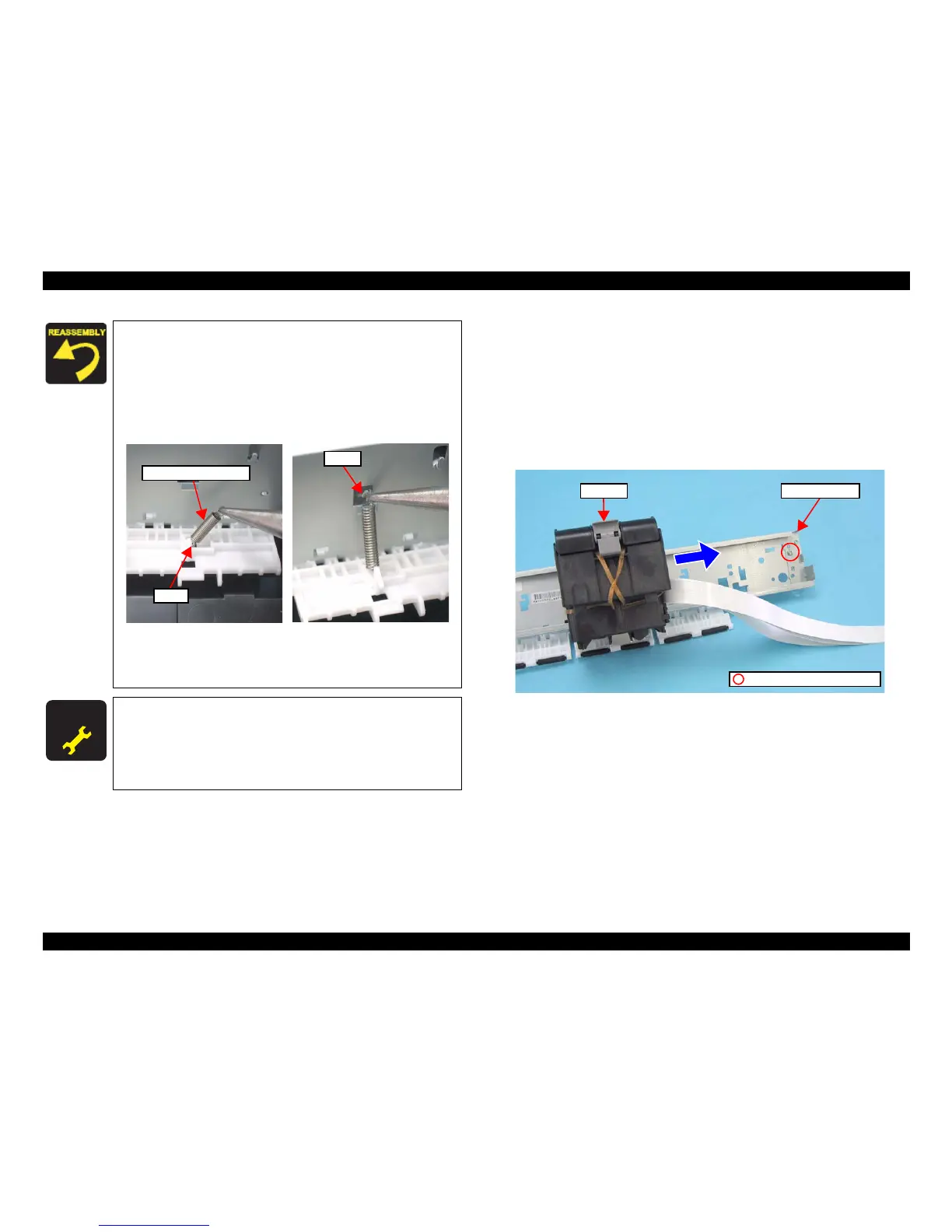
1. Remove the screw (x1) that secures the CR Scale Holder, and remove it.
2. Move the CR Unit in the direction of the arrow to remove the unit.
Figure 4-63. Removing CR Unit (1)
Tighten the screws in the order given in Figure 4-60.
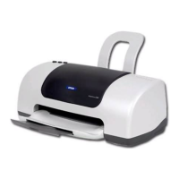
Follow the steps below to install the Extension Spring 10.99 to
the Upper Paper Guide.
1. Attach the one end of the Extension Spring 10.99 to the
hook of the Upper Paper Guide.
2. Attach the another end of the Extension Spring 10.99 to the
hook of the Main Frame with a longnose plier.
Figure 4-62. Installing Extension Spring 10.99
Be sure to install the Grounding Spring referring to Figure
4-49 and Figure 4-52.
After replacing the Main Frame, be sure to perform the
specified adjustment. See
Chapter 5 “ ADJUSTMENT”
(p.107)
After replacing the Main Frame, be sure to perform the
specified lubrication. See
Chapter 6 “ MAINTENANCE”
(p.116)