EPSON Stylus C110/C120/D120 Revision B
DISASSEMBLY/ASSEMBLY Removing Board 76
4.4 Removing Board
4.4.1 Main Board Unit/Left Frame
Part/Unit that should be removed before removing Main Board Unit/Left
Frame
Upper Housing
Removal Procedure
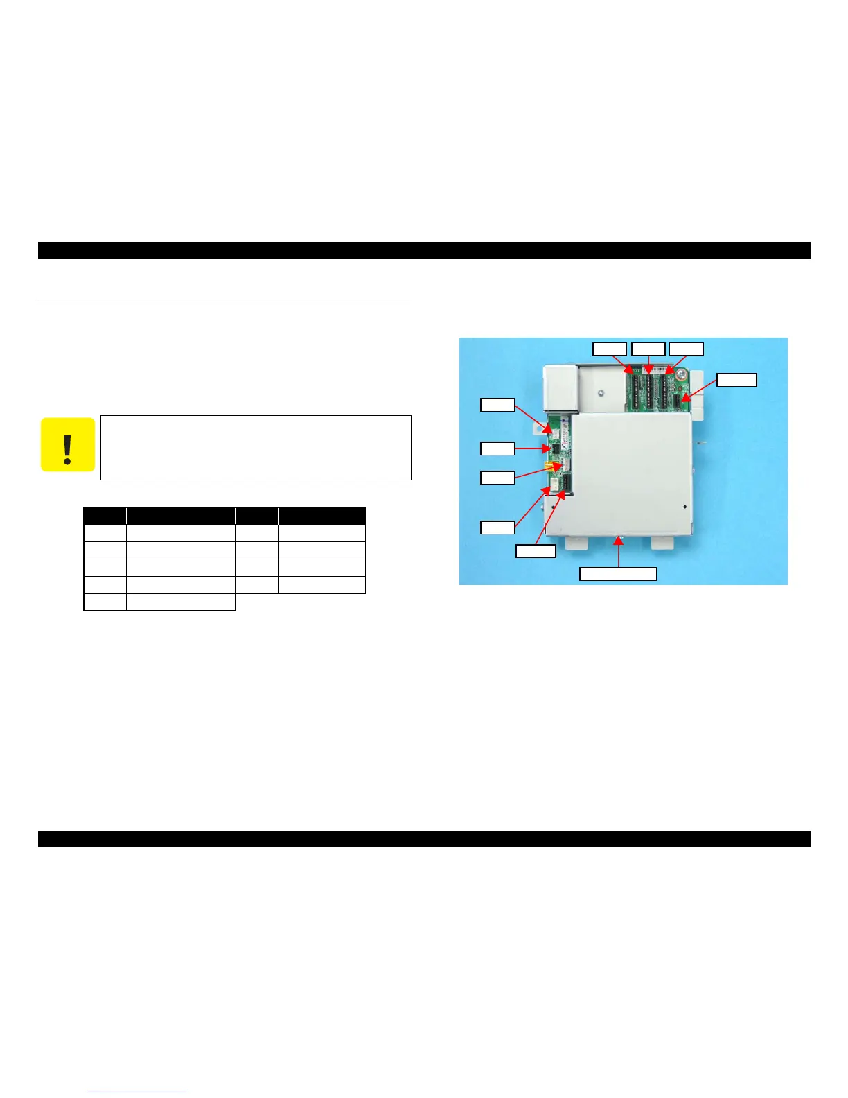
1. Disconnect the following connectors (x4) and FFCs (x5) from the Main Board.
Figure 4-9. Connector Layout of Main Board
Be careful not to bend or damage the Panel Unit FFC when
removing it.
CN No. Cable CN No. Cable
CN1 Power Supply Unit cable CN8 CR Motor cable
CN3 PE Sensor cable CN9 PF Motor cable
CN5 Head FFC CN10 PF Encoder FFC
CN6 Head FFC CN11 Panel Unit FFC
CN7 Head FFC