EPSON Stylus C110/C120/D120 Revision B
OPERATING PRINCIPLE Electrical Circuit Operating Principles 39
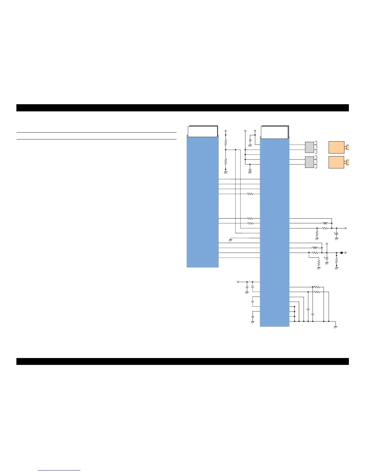
2.3.2.3 Motor Driver Circuit
CR/PF MOTOR DRIVE CIRCUIT
The motor driver IC (IC5) on the main board drives CR/PF motors. The both motors
are DC motor and are controlled by constant current PWM drive method.
Based on the output pulse (signal) from the CR encoder or PF encoder, the CPU (IC8)
sets the appropriate drive voltage for the current operation and outputs the value as a
special control signal to the motor driver (IC5). Then, based on the signal output from
the CPU, the motor driver applies the corresponding motor drive voltage to the CR/PF
motor.
When no data has been received for 5 minutes, the CPU sets the motor driver voltage to
0, and turn the motor driver Off to save power.
Figure 2-21. Motor Driver Circuit Block Diagram