EPSON Stylus C110/C120/D120 Revision B
OPERATING PRINCIPLE Electrical Circuit Operating Principles 40
2.3.2.4 Reset Circuit/EEPROM Circuit
RESET CIRCUIT
The reset IC (IC3) monitors +3.3V on the logic line and +42V on the drive line. It
outputs a reset signal to the CPU (IC8) in the cases described below.
+3.3V line reset circuit
IC3 monitors 3.3V line through Vi2 port, and transmits a reset signal to the CPU
through Vo2 port if it detects an abnormal voltage.
+42V line reset circuit
IC3 monitors 42V line through Vi1 port, and transmits a reset signal to the CPU
through Vo1 port if it detects an abnormal voltage.
EEPROM CONTROL CIRCUIT
EEPROM is a nonvolatile memory that keeps data written to it even after the power-
off. The CPU (IC8) reads data from the EEPROM (IC4) in the power-on sequence, and
stores data into the EEPROM in the power-off sequence.
EEPROM stores the following information.
Ink counter
(Ink consumption in ink cartridges, Waste ink pad counter, etc.)
Mechanical settings
(Head ID, Bi-D adjusted settings, USB ID, etc.)
EEPROM is connected to the CPU with the four lines. Each of the lines are used for
data transmission as shown below.
CE : Chip selection signal
CLK: Data synchronization clock pulse
DI: Data to be written at power-off (serial data)
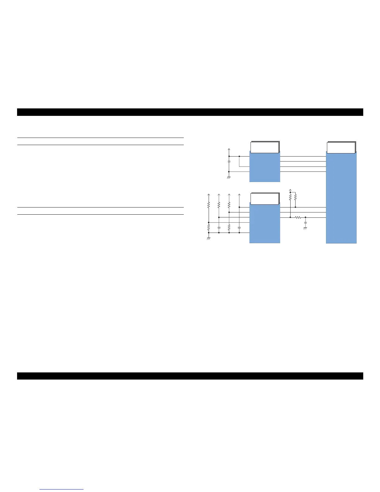
DO : Data to be read at power-on (serial data)
Figure 2-22. Reset/EEPROM Circuit Block Diagram