EPSON Stylus C110/C120/D120 Revision B
OPERATING PRINCIPLE Electrical Circuit Operating Principles 41
2.3.2.5 Sensor Circuit
CPU (IC8) on the main board monitors the status of the printer by several sensors.
However, unlike the previous product, ASF unit on this printer does not have ASF
Sensor. Instead of ASF Sensor, Change Lever and the Clutch mechanism is used to
detect ASF home position. (As for the ASF home position detection, refer to
“ 2.2.3
Paper Loading/Paper Feed Mechanism ” (p.26).
PE Sensor
This sensor is mounted at the right side center of the printer mechanism in order to
detect the presence/absence of paper when the paper passes through the Upper
Paper Guide.
Paper Absent: Light emitted from the light-emitting device of the sensor is
received by the light-receiving side of the sensor without
interrupted by paper. A LOW signal is output to the CPU.
Paper Present: Light emitted from the light-emitting device of the sensor is
interrupted by paper. A HIGH signal is output to the CPU.
CR Encoder Sensor
The sensor consists of the two devices; a transmissive photosensor mounted on the
back of the carriage and a linear scale attached along the carriage movement range.
Fine black lines are printed on the linear scale in 1/180 inch of the minimum
resolution. The photosensor outputs HIGH signal to the CPU each time it reads the
black line, and outputs LOW signal each time it reads the non-printed area. The
CPU controls the CR motor based on the signals. The carriage unit home position
is also detected by the sensor.
PF Encoder Sensor
The sensor consists of the two devices; a transmissive photosensor mounted on the
main board and a rotary scale attached at the left of the PF Roller Unit. Fine black
lines are printed on the rotary scale in 1/180 inch of the minimum resolution. The
photosensor outputs HIGH signal to the CPU each time it reads the black line, and
outputs LOW signal each time it reads the non-printed area. The CPU controls the
PF motor based on the signals.
Thermistor (THM)
The thermistor is directly mounted on the printhead drive board. It monitors the
temperature around the printhead and determines a proper head drive voltage
according to the detected temperature. This information is fed back to the CPU
analog port. When the temperature rises, the head drive circuit lowers the drive
voltage, and when the temperature lowers, the head drive circuit rises the drive
voltage.
Cover Open Sensor
This sensor is mounted on the backside of the upper housing (far left) and detects
whether the printer cover is opened or closed.
Cover is opened: a HIGH signal is output to the CPU.
Cover is closed: a LOW signal is output to the CPU.
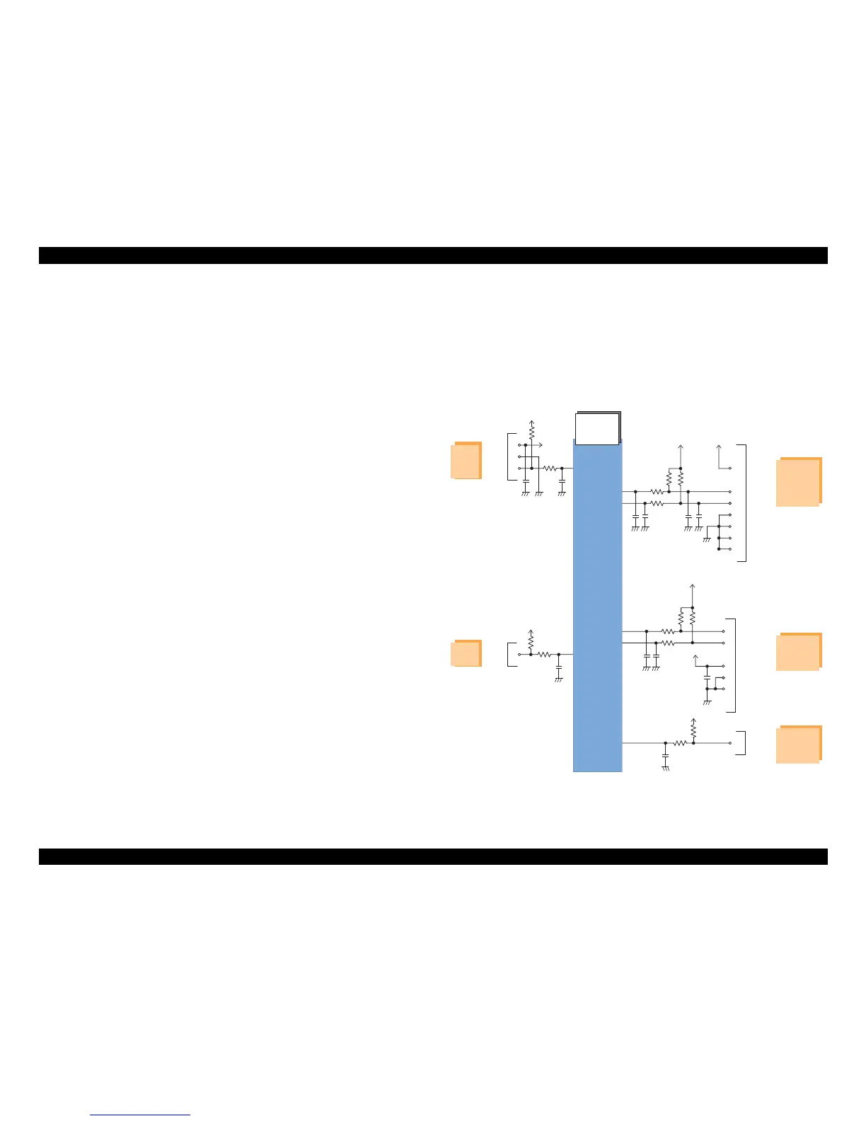
The block diagram for the sensor circuit is shown below.
:
Figure 2-23. Sensor Circuit Block Diagram