EPSON Stylus CX4100/CX4200/CX4700/CX4800/DX4200/DX4800/DX4850 Revision A
DISASSEMBLY/ASSEMBLY Printer Section 149
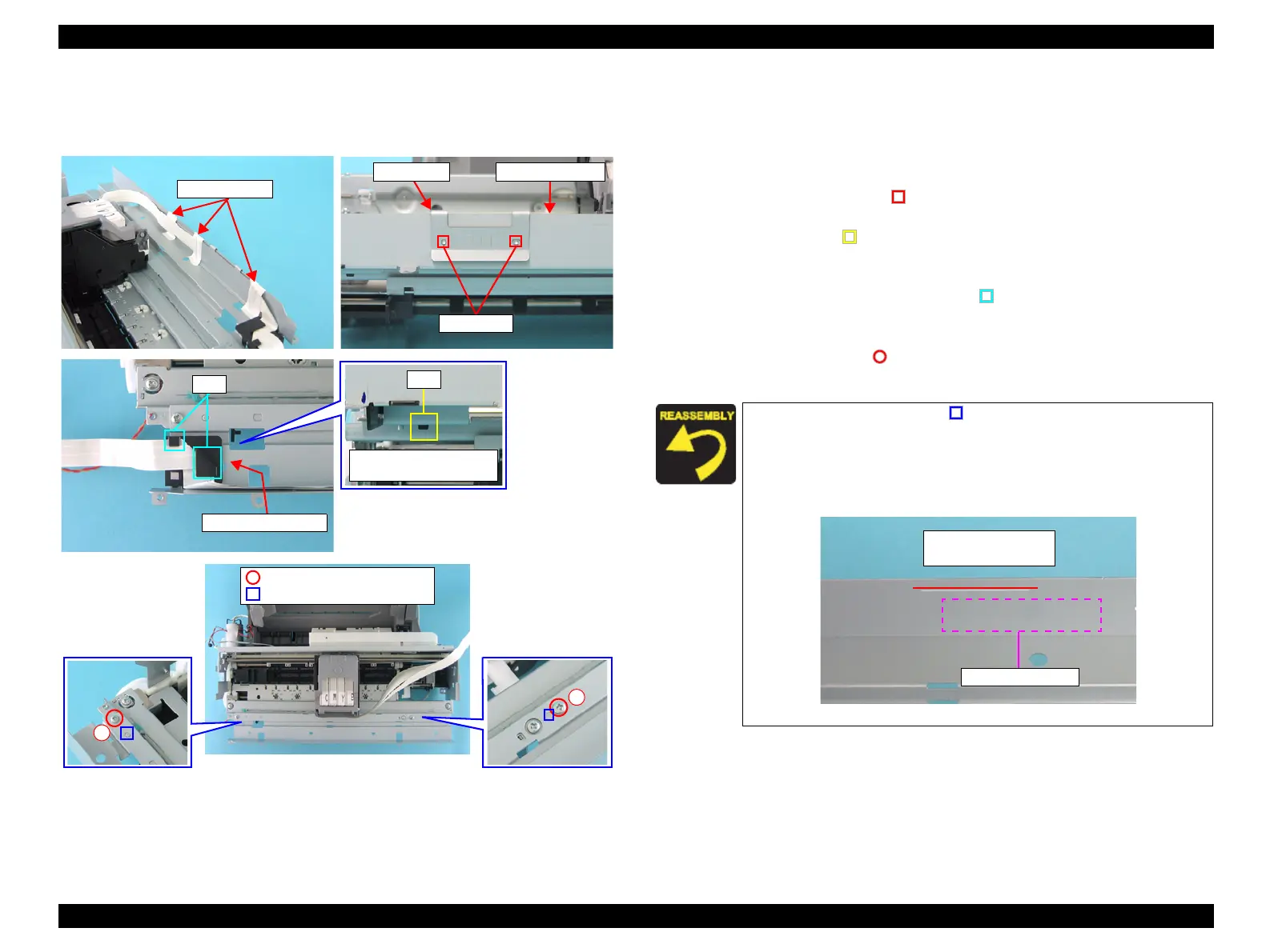
4.4.16 CR Guide Frame
External view
Figure 4-30. Removing CR Guide Frame
Part/Unit that should be removed before removing CR Guide Frame
Document Cover / Paper Support Assy. / Scanner Unit / Panel Unit /
Housing, Upper / Printer Mechanism / Main Board Unit
Removal procedure
1. Peel off the acetate tape (x3) that secure the Head FFCs (x3).
2. Release the guide pins (x2, ) that secure the FFC Guide, and remove the
FFC Guide from the CR Guide Frame.
3. Release the tab (x1, ) on the bottom of the CR Guide Frame that secures the
FFC Frame Holder, and remove the FFC Frame Holder together with the
Head FFC.
4. Release the Head FFC from the tabs (x2, ) of the FFC Frame Holder.
5. Release the Head FFCs (x3) secured with the double-sided tape (x1) from the
CR Guide Frame.
6. Remove the screws (x2, ) that secure the CR Guide Frame, and remove the
CR Guide Frame from the Printer Mechanism.
Acetate Tapes
FFC Guide
Guide Pins
CR Guide Frame
FFC Frame Holder
Tab
Tab
Downside of CR Guide
Frame
C.B.S. 3x6 F/Zn (7±1kgfcm)
Guide Pins
2
1
Match the guide pins (x2, ) of the Front Frame with the
positioning holes (x2) of the CR Guide Frame.
Tighten the screws in the order as shown in the figure.
Attach the Head FFCs (x3) with double-sided tape to the position
on the CR Guide Frame indicated with printed lines.
Figure 4-31. Attaching Head FFCs
Double-sided Tape
Printed Lines
(Installation Position)
 Loading...


