EPSON Stylus CX4100/CX4200/CX4700/CX4800/DX4200/DX4800/DX4850 Revision A
APPENDIX Connector Summary 195
7.1 Connector Summary
7.1.1 Major Component Unit
The major component units of this printer are as follows.
Main Board (C610 Main)
Power Supply Board (C610 PSB/PSE)
Panel Board (C571 PNL/C577 PNL)
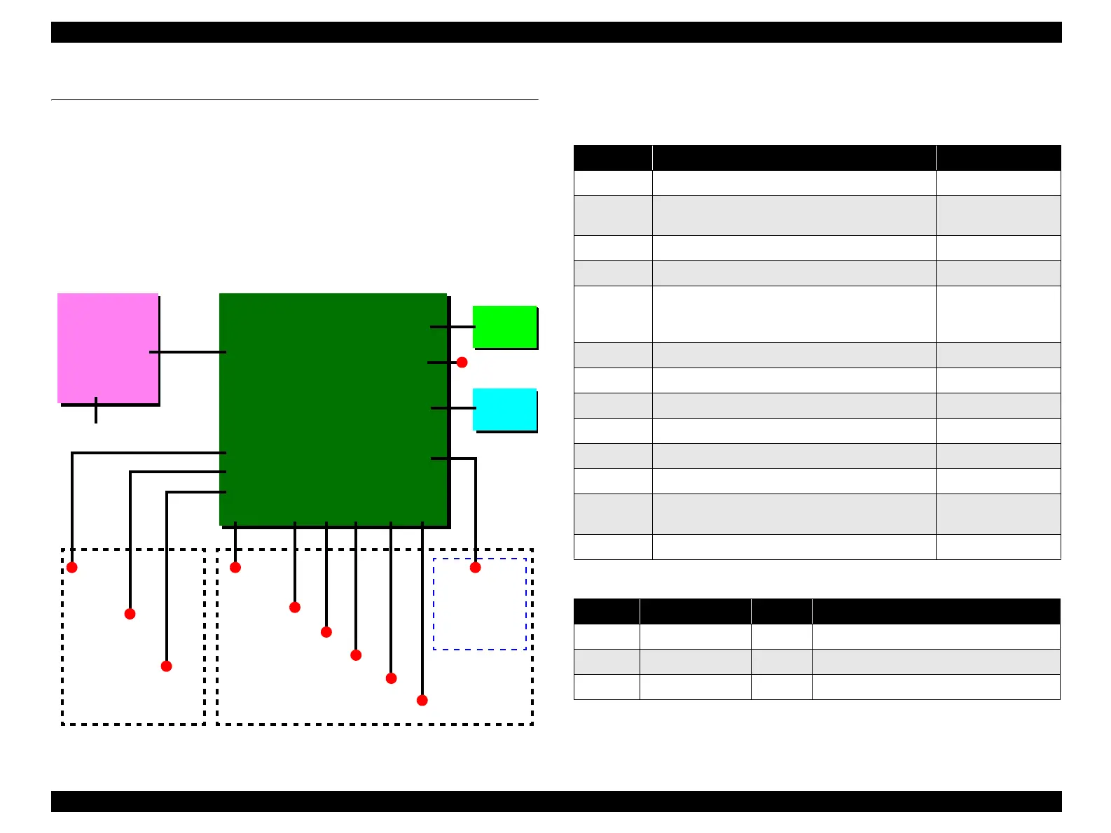
The figure below shows how to connect these components.
Figure 7-1. Connection of the major components
See the following tables for the connector summary for the C610 Main board and each
connectors pin alignment.
P1
PF Encoder
Sensor
C610 Main
CN3
CN1
C610 PSB/PSE
CN2
AC power
Printer
Mechanism
USB2.0 I/F
CN2
CN13
CN11
CN10
Scanner HP
Sensor
Scanner
Carriage FFC
Scanner Motor
Scanner
Mechanism
PE Sensor
CN4
PG Sensor
CN5,
CN6,
CN7
Print Head
CN8
CR Motor
CN12
CN9
PF Motor
C571 PNL/
C577 PNL
CN14/CN15
Memory
Card
Only for Stylus
CX4700/CX4800/
DX4800/DX4850
CN16
USB Host
I/F Board
Table 7-1. Connector Summary for C610 Main Board
Connector Function Table to refer to
CN1 For connection with the Power Supply Board Table 7-2 (p.195)
CN2 For connection with the USB2.0 interface
“1.3.1 USB
Interface” (p.24)
CN3 For connection with the PE Sensor Table 7-3 (p.196)
CN4 For connection with the PG Sensor Table 7-4 (p.196)
CN5 to CN7 For connection with the Print Head
Table 7-5 (p.196),
Table 7-6 (p.196),
Table 7-7 (p.197)
CN8 For connection with the CR Motor Table 7-8 (p.197)
CN9 For connection with the PF Motor Table 7-9 (p.197)
CN10 For connection with the Scanner Motor Table 7-10 (p.197)
CN11 For connection with the Scanner Carriage FFC Table 7-11 (p.197)
CN12 For connection with the Panel Board Table 7-12 (p.198)
CN13 For connection with the Scanner HP Sensor Table 7-13 (p.198)
CN14/CN15 For connection with the Memory Card
Table 7-14 (p.198),
Table 7-15 (p.199)
CN16 For connection with the USB Host I/F Board Table 7-16 (p.200)
Table 7-2. CN1 - Power Supply Board
Pin Signal Name I/O Function
1 +42V — +42V
2 GND — Ground
3 PSC I Power supply control
 Loading...


