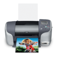
EPSON Stylus Photo 925 Revision A
Disassembly and Assembly Disassembly 105
4.2.15 Ink System Unit removal
1. Remove the Housing from the printer. (Refer to 4.2.1 “Housing removal”)
2. Remove the Housing lower cover from the printer. (Refer to 4.2.3 “Housing Lower
Covers removal”)
3. Remove the LD roller shaft holder from the printer. (Refer to 4.2.7 “LD Roller
removal”)
4. Remove the ASF unit from the printer. (Refer to 4.2.9 “ASF Unit removal”)
5. Remove the ASF motor from the printer. (Refer to 4.2.12 “ASF Motor removal”)
6. Remove the Circuit board from the printer. (Refer to 4.2.14 “Circuit Board Unit
removal”)
7. Remove the one screw (C.B.S. SCREW, 3x6, F/ZN) securing the Ink System Tray
to the printer body, and remove the Ink System Tray.
Figure 4-66. Removing the Ink System Tray
8. Remove the four screws (C.B.S. SCREW, 3x6, F/ZN and C.B.S. SCREW, 3x4, F/
UC) securing the Ink System Frame to the Main Frame.
Figure 4-67. Removing the Ink System Unit
9. Remove the Ink System Unit (Cap/Pump Unit) carefully.
10. Disengage the hooks fastening the Cap Unit to the Ink System Frame, and remove
the Cap Unit. (Refer to Figure 4-68. “Removing the Cap unit”)
11. Disconnect the ink tube carefully from the bottom of the Cap unit.
Figure 4-68. Removing the Cap unit
C.B.S. SCREW, 3x6, F/ZN
Ink System Tray
C A U T I O N
T When the Ink system unit is removed, be careful that the gears
do not come off from each shaft on the Ink system frame.
C.B.S.SCREW, 3x6, F/ZN
C.B.S, SCREW, 3x4, F/UC
Cap Unit
Hooks
Ink Tube

 Loading...


