EPSON Stylus CX7300/CX7400/DX7400/NX200/TX200 series/SX200 series/Stylus CX8300/CX8400/DX8400/NX400/TX400 series/SX400 series Revision C
OPERATING PRINCIPLES Overview 44
Confidential
2.1.3 Printhead
D4-CHIPS Turbo2 type printhead is employed, which produces variable sized dot and
economy dot. The printhead configuration is as follows.
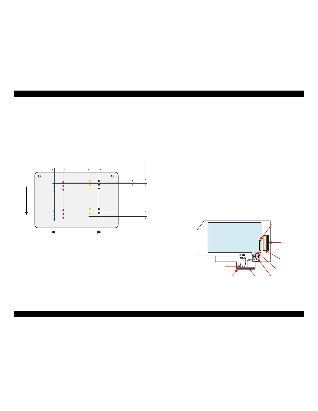
Nozzle configuration
Black: 90 nozzles x 1
Color: 90 nozzles x 3 (cyan, magenta, yellow)
The nozzle layout as seen from behind the printhead is shown below.
Figure 2-4. Nozzle Layout
The basic operating principles of the printhead, which plays a major role in printing,
are the same as the previous printer; on-demand method which uses PZT (Piezo
Electric Element). In order to reduce unit-to-unit variation in ink droplet size, the
printhead has its own Head ID (16-digits code for EPSON Stylus CX7300/CX7400/
DX7400/NX200/TX200/TX203/TX209/SX200/SX205 and Stylus CX8300/CX8400/
DX8400/NX400/TX400/TX405/TX409/SX400/SX405) which corrects PZT drive
voltage for the printhead.
Therefore, whenever the printhead, main board, or the printer mechanism must be
replaced with a new one, the Head ID of the new printhead needs to be written into the
EEPROM using the Adjustment Program. The printer generates appropriate PZT drive
voltage based on the Head ID information.
Following explains the basic components of the Printhead.
PZT
PZT is an abbreviation of Piezo Electric Element. Based on the drive waveform
generated on the main board, the PZT selected by the nozzle selector IC on the
printhead pushes the top of the ink cavity, which has ink stored, to eject the ink
from each nozzle on the nozzle plate.
Nozzle Plate
The plate with nozzle holes on the printhead surface is called Nozzle Plate.
Filter
This filter is located beneath the ink supply needle which supply ink to the
printhead from the ink cartridge. The filter is preventing dirt or dust from getting
into the printhead. Any dirt or dust may interrupt normal ink flow or can cause
nozzle clog adversely affecting the print quality.
Ink Cavity
The ink absorbed from the ink cartridge goes through the filter and then is stored
temporarily in this tank called “ink cavity” until PZT is driven.
Figure 2-5. Printhead Mechanism