EPSON Stylus CX7300/CX7400/DX7400/NX200/TX200 series/SX200 series/Stylus CX8300/CX8400/DX8400/NX400/TX400 series/SX400 series Revision C
DISASSEMBLY/ASSEMBLY Disassembling the Printer Mechanism 119
Confidential
4.5.11 PF Motor
Parts/Components need to be removed in advance
Document Cover/ASF Cover/Scanner Unit/Panel Unit/Upper Housing/Card Slot
Cover/
Lower Housing
/Main Board Unit/Left Frame/PF Encoder Sensor/PF Scale
Removal procedure
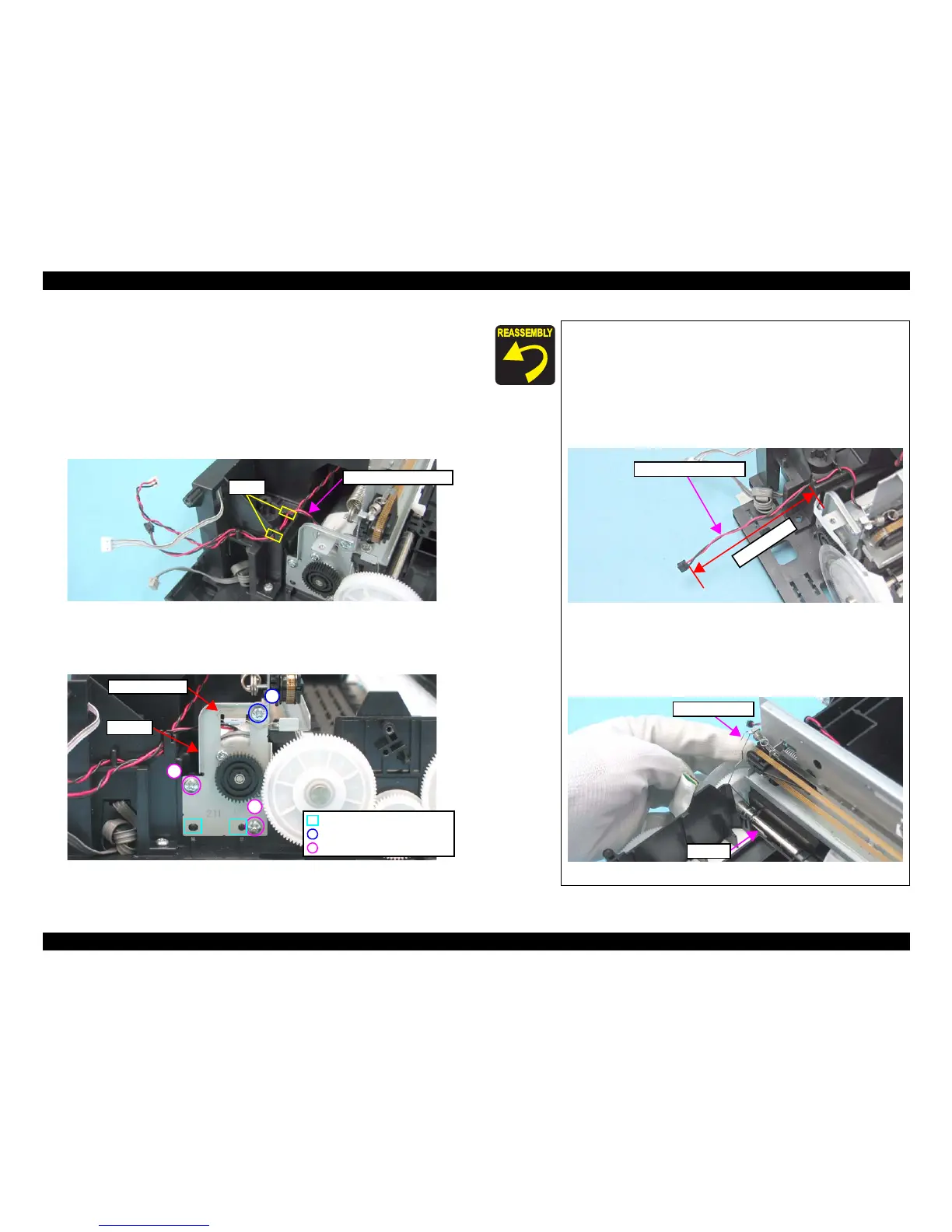
1. Release the PF Motor connector cable from the notches (x2) of the Base
Frame.
Figure 4-61. Removing the PF Motor (1)
2. Remove the Grounding Spring from the PF Motor.
3. Remove the screws (x3) that secure the PF Motor, and remove it.
Figure 4-62. Removing the PF Motor (2)
Notch
PF Motor Connector Cable
C.B.P. 3x8, F/Zn-3C (6±1kgfcm)
Grounding Spring
PF Motor
Guide Pin and Positioning Hole
1
2
C.B.S. 3x6, F/Zn-3C (8±1kgfcm)
3
When installing the PF Motor, pay attention to the following
instructions.
• Do not damage the PF Scale.
• Insert the guide pins (x2) on the Base Frame into the
positioning holes (x2) of the PF Motor as shown in
Figure
4-62.
• Route the PF Motor Connector Cable as shown in the figure
below.
Figure 4-63. Routing the PF Motor Connector Cable
Tighten the screws in the order given in Figure 4-62.
Follow the steps below to install the Grounding Spring.
1. Attach the larger U-shaped end of the Grounding Spring
to the PF Roller.
Figure 4-64. Installing the Grounding Spring (1)
PF Motor connector cable
7
1
m
m
o
r
m
o
r
e
Grounding Spring
PF Roller
 Loading...