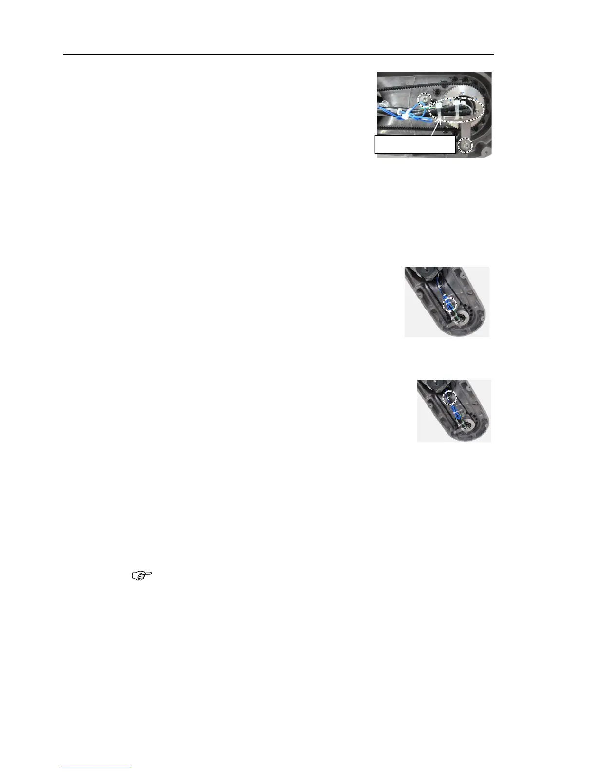
Maintenance 10. Joint #2
182 VT Rev.1
Mount the cable fixing plate on
the Arm #2.
(Joint #2 side)
Hexagon socket head cap bolts: 2-M4×12
(with a washer)
Tightening torque: 4.0 ± 0.2 N·m
the following cables and the ground wire with the
Wire tie: AB150
Motor cable
Signal cable (for motor)
LED cable
Ground wire
the brake cable of Joint #2 motor into the length of
the following cables with the wire
Wire tie: AB100
Power cable
Signal cable (for motor)
Brake cable
the mount base inside the Arm #2.
the following cables with the wire tie.
Wire tie: AB100
Power cable
Signal cable (for motor)
Brake cable
LED cable (mount base A only)
ount the Arm #2 cover.
Reference: Maintenance 7.2 Arm #2 Cover
the Manipulator.
Reference: Setup & Operation 6.5 LED
When starting the manipulator for the first time after replacing the motor unit, the
motor unit firmware is automatically updated.
DO NOT turn OFF the manipulator
until it starts.
Reference: Maintenance 19. Calibration