Maintenance 8. Cable
148 VT Rev.1
8.1 Replacing Cable Unit
Maintenance
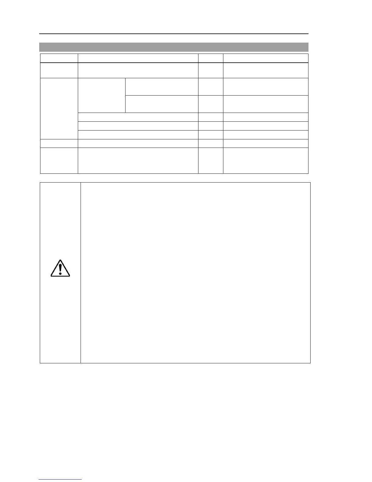
part
Cable Unit 1 2191349
Tools
Hexagonal
wrench
width across flats: 2.5 mm
1
For M3 hexagon socket head
cap bolts
width across flats: 3 mm
1
For M4
hexagon socket head
cap bolts
For tightening torque control
Cross-point screwdriver (No. 2)
Grease
GPL-224 -
For purchasing grease, please
contact the supplier in your
If the connectors have been disconnected during the replacement of the cable
unit, b
e sure to reconnect the connectors to their proper positions. Refer to the
Improper connection of the connectors may result in improper
For details on the connections, refer t
Maintenance: 3. Manipulator Structure.
When installing the cover, b
e careful not to allow the cables to interfere with the
not bend these cables forcibly to push them into the cover.
Unnecessary strain on cables may result in damage to the cables, disconnection,
and/or contact failure. Damaged cables, disconnection, or contact failure is
extremely hazardous and may result in electric shock and/or improper function of
the robot system.
routing the cables, observe the cable locations
after removing the cover.
Be sure to
place the cables back to their original locations.
Be sure to connect the cables
completely. Do not allow unnecessary strain on
put heavy objects on the cables. Do not bend or pull the
y.) The unnecessary strain on the cables may result in damage to
the cables, disconnection, and/or contact failure. Damaged cables,
disconnection, or contact failure is extremely hazardous and may result in electric
shock and/or improper function of the robot system.
When removing the Joint #2 motor unit, tilt the Arm #2 and press it against the Arm #1.
Reference: Maintenance: 10.1 Joint #2 - Replacing the Motor, Removal step (2)
When removing the Joint #3 motor unit, tilt the Arm #3 and press it against the Arm #2.
Reference: Maintenance: 11.1 Joint #3 - Replacing the Motor, Removal step (2)