Maintenance 18. Controller Unit
VT Rev.1 237
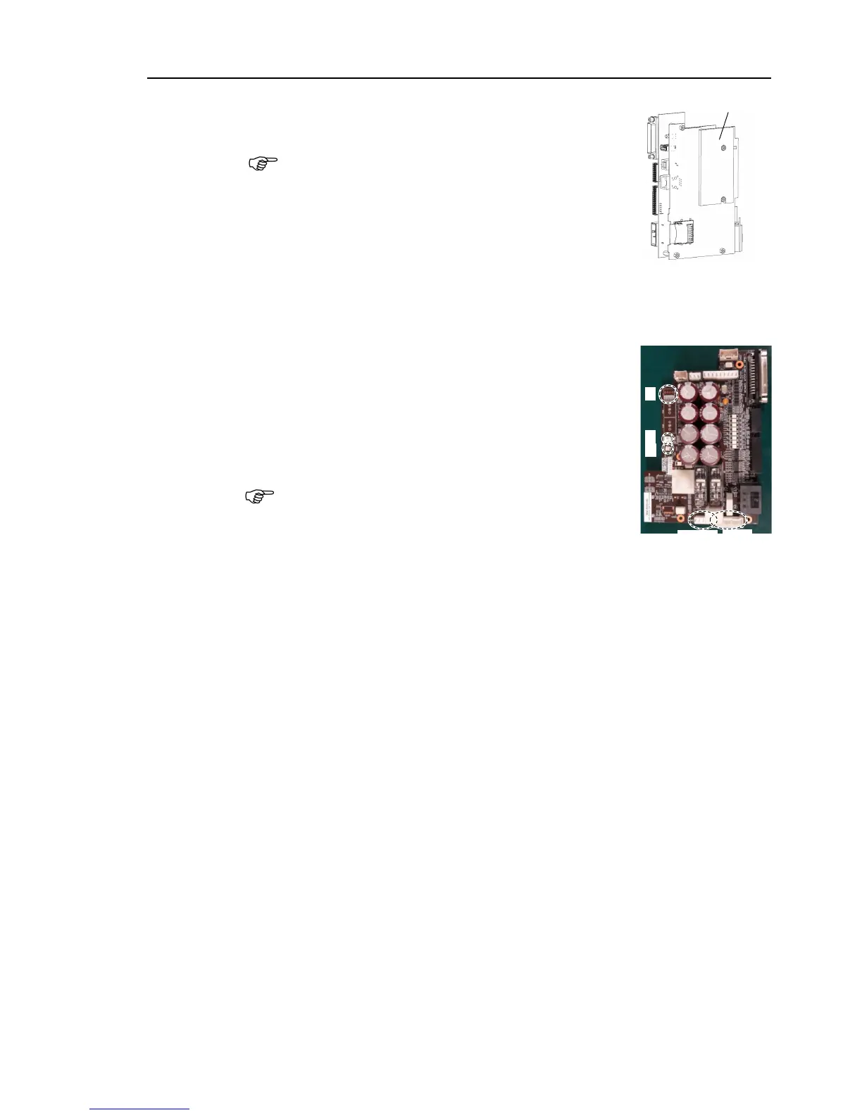
the thermal sheet on the surface (the side with no
the sheet on the wrong surface.
the CPU/DPB board and fix it by the mounting screws.
Binding head screws: 5-M3×6
Tightening torque: 0.45 ± 0.1N·m
the CPU/DPB board connectors.
E: Power connector (IN/OUT ×1 for each)
F: Cooling fan connector
G: Regenerative resistor connector 1
H: Regenerative resistor connector 2
Be careful not to connect
the wrong connectors or forget to
ount the power board.
Reference: Maintenance 18.2 Replacing Power Board