Setup & Operation 11. Options
VT Rev.1 83
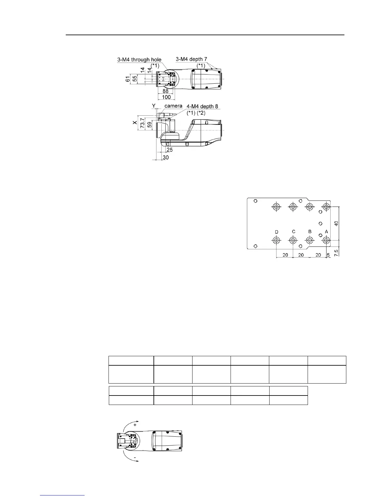
Dimensions after installing the Camera Plate Unit
*1: Available for fixing the cables
*2: Includes the opposite side
Dimensions X and Y will change depending on the position of camera mid plate and
camera size. Refer to the table below for the values.
Camera mid plate
The camera mid plate uses the mounting holes
A to D.
By using the different mounting holes, it can
be mounted to the camera base plate in the
different four positions.
Camera and VT series Manipulator Joint #5 motion range (reference values)
The Joint #5 motion range varies depending on the mounting position of camera mid plate
and the camera you are using.
The table below shows the motion range (reference values) based on the available cameras
for this option and the mounting positions of the camera mid plate. The values in the
table may vary depending on how to secure the cables.
By changing the Y position, you can extend the distance from the end effector mounting
surface to the camera. Also, you can attach the larger end effector. However, be careful
about the Joint #5 motion range that will be limited in this case.
Direction of the Joint #5 motion