3 • Description of the Controls
20 / 66
80110-801_V23493
2022-03
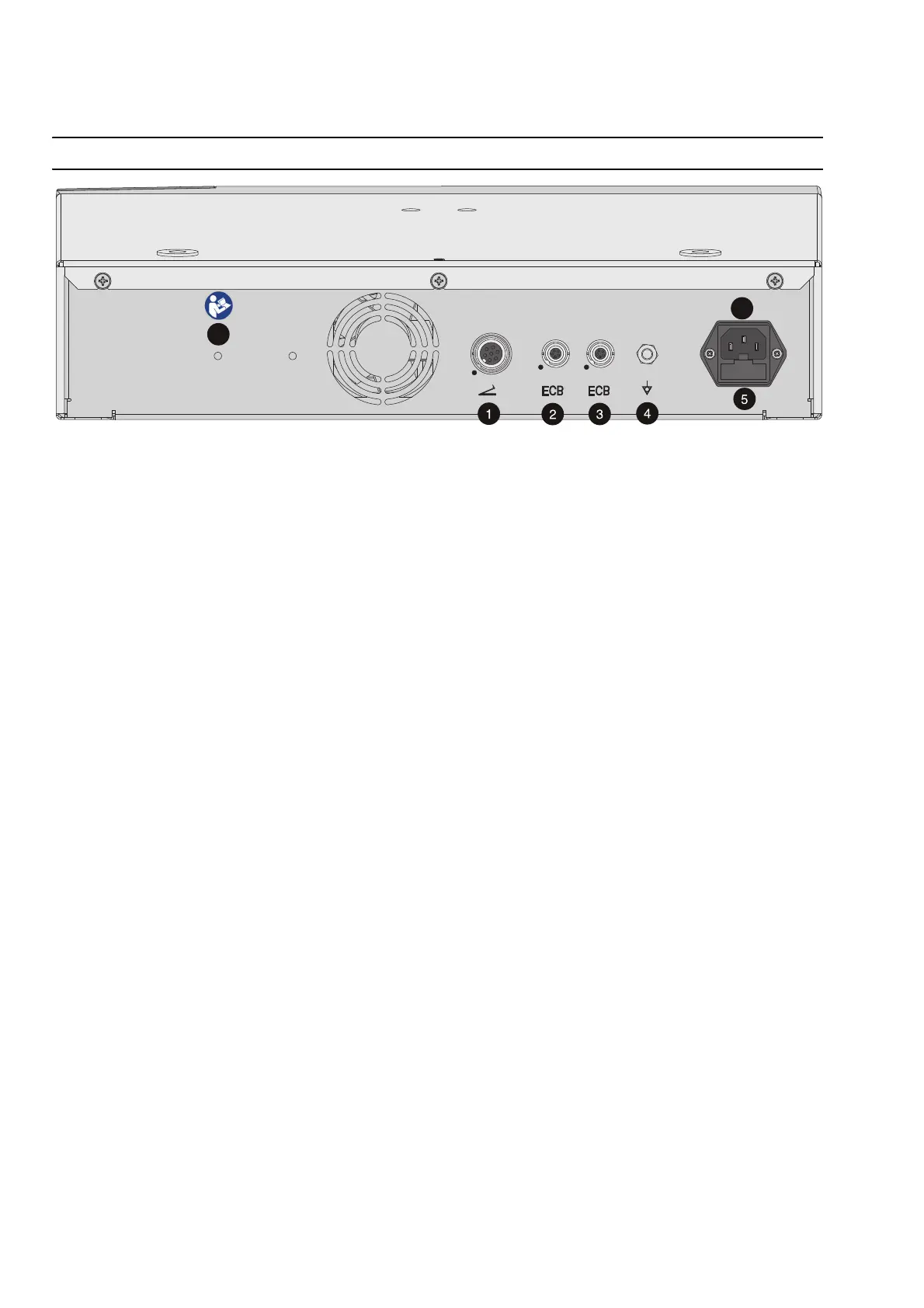
Controls on the back
Fig. 3-2
Sockets
(1) Footswitch socket
You can connect a single-pedal or a dual-pedal footswitch to this socket.
(2) (3) ECB sockets (ECB means Erbe Communication Bus)
Other compatible units can be connected to ERBEJET 2. The ECB ensures communica-
tion between the units. Connect an ECB cable with these sockets and with one of the
other units.
Potential equalization
(4) Potential equalization terminal
Attach a potential equalization line and connect this to the potential equalization sys-
tem of the operating room. If you are using the Erbe VIO-CART, connect the potential
equalization line to the potential equalization pin of the VIO-CART.
Power fuses
(5) Power fuses
The unit is protected with power fuses. If one of these power fuses has blown, the unit
may not be used on the patient again until it has been checked by a competent tech
-
nician. The values of the power fuses are specified on the unit's rating plate. Only
spare fuses with these values may be used.
Power connection
(6) Power connection
Connect the unit to a properly installed, grounded power outlet. Use the compatible
Erbe power cord (see the Accessories, Compatible power cords chapter). If the unit is
installed on the Erbe VIO CART, connect to the power supply using the VIO CART’s pow
-
er cord.
Symbol
(7)
Read the user manual before switching on and using the unit.