Installing the Equipment
Unbalanced Audio (AVP/CAB/UNBAL)
With this option four unbalanced audio channels can be connected to the
Audio/Data D-Type connector on a VCM option card. A BNC plug is provided for
each of the four analogue inputs, and a 75 Ω BNC plug for an AES3 reference
signal at 3.072 Mbps. The reference signal contains a 1 kHz tone at -6 dBFS at a
sample rate of 48 kHz.
Table 2.22 Analogue Audio Input (Unbalanced)
Item Specification
Connector types 15-way D-Type
Connector designation AUDIO/DATA
Pin Outs Analogue 1 – 1
Analogue 1 – Shell
Analogue 2 – 1
Analogue 2 – Shell
Analogue 3 – 1
Analogue 3 – Shell
Analogue 4 – 1
Analogue 4 – Shell
Ref – 1
Ref - Shell
1
9
10
3
4
12
13
6
7
15
Audio 1 Line
Screen
Audio 2 Line
Screen
Audio 3 Line
Screen
Audio 4 Line
Screen
AES3 Reference (48 kHz)
Screen
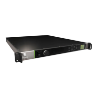
2.3.5 Satellite Modulator Option Card Connectors
The Satellite Modulator Option Card takes MPEG Transport Streams on its input
and provides a modulated output either in L-band (950 – 2150 MHz) or in IF band
(80 – 150 MHz) according to the DVB-S, DVB-DSNG, DVB-S2 or DVB-S2X
specification.
The output signal can be fed to an up-converter for mixing the signal to the
appropriate satellite channel. The module is also capable of powering the
downstream up-converter. The module can take two input Transport Streams and
encode and modulate one of them at a time. If the Transport Stream being
modulated is lost for some reason, the module can switch automatically to the other
Transport Stream input and continue the transmission using that. The L-band input
can be used for inputting a modulated L-band signal to the module. The module
then can combine the input and its own modulated output and feed a common up-
converter with the combined signal.
Figure 2.3 Satellite Modulator Option Card Rear Panel