6-18 TROUBLESHOOTING Manual 0463 413 001
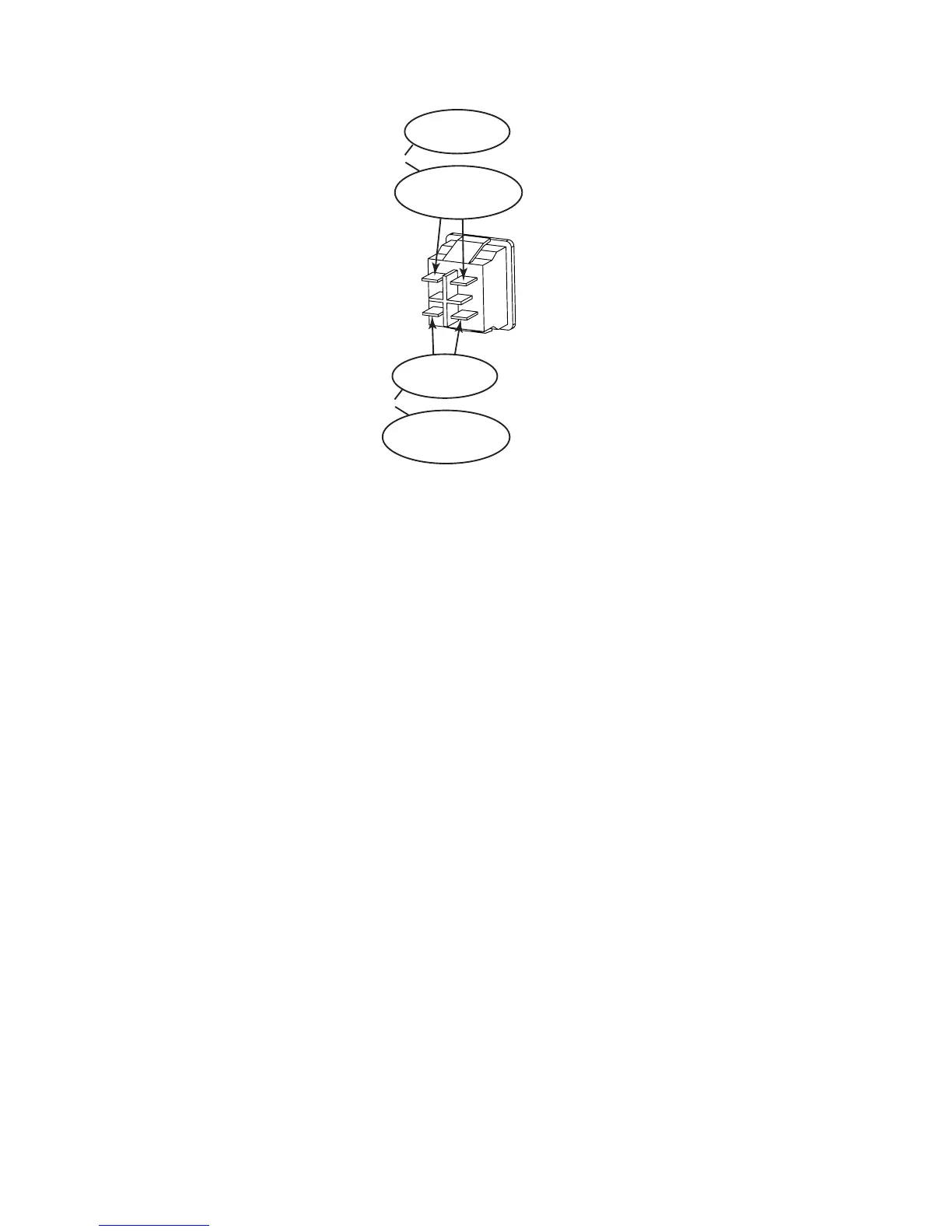
The following image shows the previous steps listed. In the oval you will see the step number and below that
the meter reading you should see.
2b
120VAC +/- 10%
2b
208/230VAC +/- 10%
OR
2c
120VAC +/- 10%
2c
208/230VAC +/- 10%
OR
3. Front Panel Display is o, but OCV is present on output weld terminals.
a) Connector unplugged from either CN3 on USER INTERFACE PCB1 or CN6 on CONTROL PCB3 or
there is an open wire between them.
b) Defective USER INTERFACE PCB1
4) OVER TEMPERATURE symbol displayed on panel
There are four (4) NTC Thermal Devices in the unit. If the unit is experiencing an over heating issue, the
NTCs will prevent damage to the unit. Two are part of the POWER PCB2; one located on the heatsink
for the PFC Transistor, the other on the heatsink for the switching transistors Q3,4,6,7. The Third is
located on the Main Transformer T1. The forth is on the heatsink on the OUTPUT DIODE PCB4.
When these devices are heated they will enable the OVERTEMP Protection to disable the output of the
unit. The OVER TEMPERATURE symbol will appear on the TFT Display and the Fan will turn on. When
the error is displayed, the unit should remain powered on allowing the fans to run, properly cooling the
unit components.
If the unit OVER TEMPERATURE error remains active when the unit has been allowed to cool, then the
unit has a failure.
a) Defective NTC3
Disconnect harness plug from CN7 from POWER PCB2. Measure for approx.. 12K Ohms on the har-
ness plug. Replace if defective.
b) Defective NTC4
Disconnect the harness plug from CN3 connector on OUTPUT DIODE PCB4. Measure for approx. 12K
Ohms on the CN3 connector on the pcb. Replace OUTPUT DIODE PCB4 if defective.
 Loading...