Manual 0463 413 001 TROUBLESHOOTING 6-27
OUTPUT DIODE PCB4 Test
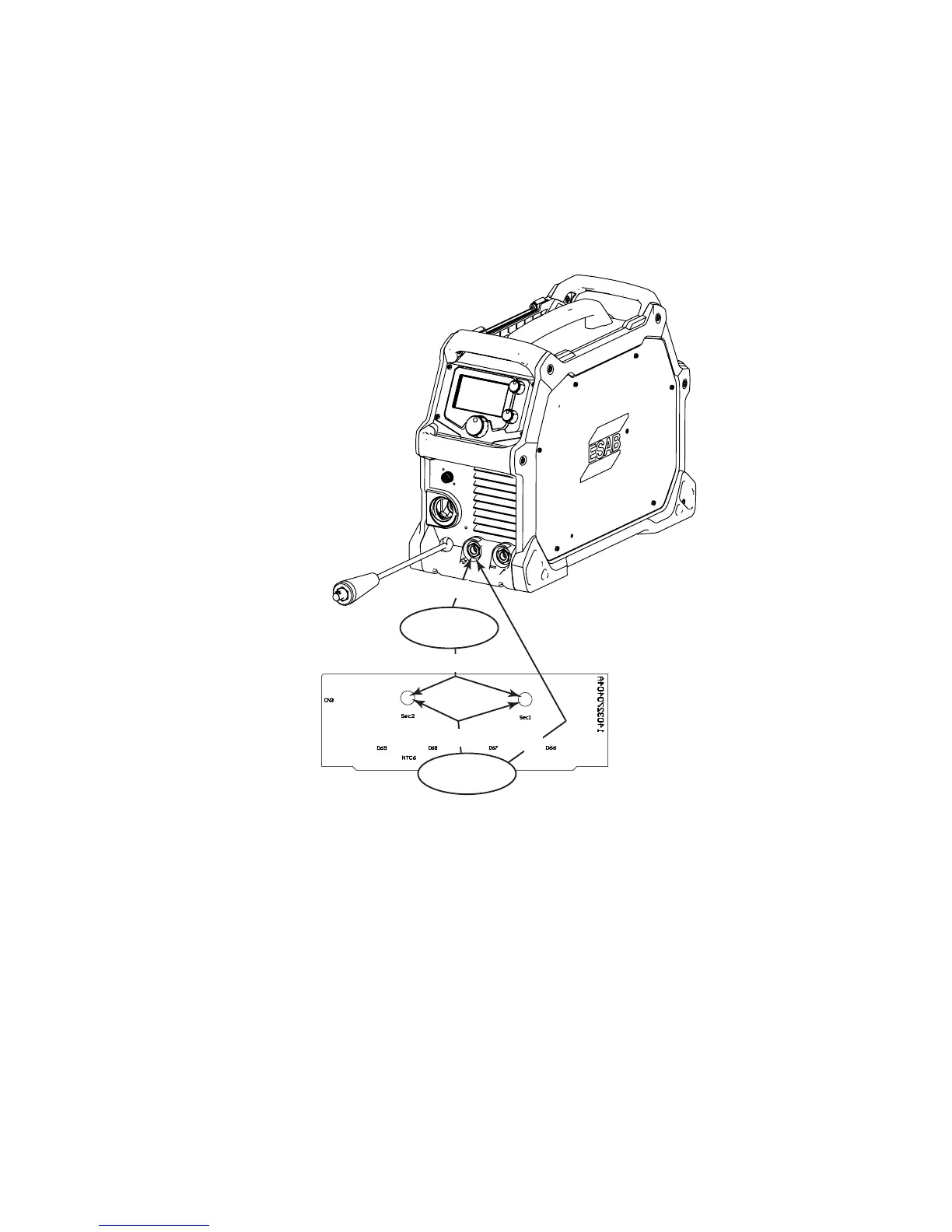
1) Disconnect and isolate T1 transformer wires from Terminals SEC1 & SEC2.
2) With negative meter lead on + Welding Output Connector, place positive meter lead on SEC1, then
SEC2 terminal. Check for forward biased diode drop reading.
3) With positive meter lead on + Welding Output Connector place negative meter lead on SEC1, then
SEC2 terminal. Check for reverse biased diode drop reading.
If an open or short is found, Replace OUTPUT DIODE PCB4.
The following image shows the previous steps listed. In the oval you will see the step number and below that
the meter reading you should see.
2
0.3 - 0.7 VDC
3
Open /Innity
+
-
+
-
CURRENT SENSOR CS1 Test
1) At CN18 connector on PCB3, use Pin 4 as a common and measure for +15VDC on Pin 1 and measure
for -15VDC on Pin 2.
If either voltage is low or missing, replace CONTROL PCB2
2) Measure voltage from Pin 4 to Pin 3. Voltage with no current flow should measure 0VDC.
3) Measure voltage from Pin 4 to Pin 3. When weld current is flowing, the voltage measured should be
approx. 0.5VDC / 100A output. Use an external ammeter to verify actual current flow as a reference.
If problem is found replace CS1.
 Loading...