PVDF PTFE TFE/P
CERAMIC
TFE/P
PVDF PE / PVC PP
INSTALLATION
Introduction
This section describes the steps for installing the pump, the pipes, and the electrical wiring. Read these
instructions carefully before beginning any activity.
Follow these guidelines when installing the pump.
• Ensure that the pump and all related equipment is turned off before starting work.
• If you encounter abnormalities or warning signals, stop immediately. Only start work again when you are
absolutely sure that you have removed the cause of the problem.
• Do not install the pump in hazardous locations or in areas at risk of fire or explosion.
• Avoid electrical hazards and fluid leakage. Never use a damaged or defective pump.
Pump installation
Install the pump away from heat sources and in a dry place at a maximum ambient temperature of 40 ° C. The
minimum temperature, not lower however than 0 ° C, depends on the type of liquid to be metered, which must always
remain in a liquid state. To fasten the pump use the supplied screw anchors, or those most suited to the support type
chosen.
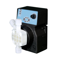
The pump can be installed either above or below the liquid level in the tank. Usually in the case of installation above
the tank, limit the suction height to within 1.5 metres of the liquid level. (see fig. 2a). For liquids that generate aggressive
vapours, do not install the pump into direct contact with the fumes and adopt the necessary precautions to prevent early
deterioration of the equipment.
In the case of installation below, i.e. with the pump positioned below the liquid level of the tank (Fig. 2b), siphoning
may occur. Periodically check the functionality of the injection valve, as excessive wear may lead to the additive
falling into the plant even with the pump turned off. If the problem persists, fit a back pressure valve C suitably
calibrated between the metering pump and the injection point as shown in Fig. 2b
Fig. 2a Fig. 2b