Both on the flow pipe and the suction pipe avoid excessive curves in order to prevent bottlenecks in the pipe itself.
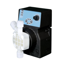
In the point most suitable for the injection of the product to be dispensed, apply a 3/8" fitting or a ½" female gas thread on
the conduct of the plant to be treated. This fitting is not supplied. Screw the injection valve to the "gasket fitting" using
PTFE tape, see Fig 7. Connect the tube to the conical injection valve and secure it with the locking ring (4). The injection
valve is also a non-return valve.
1. plant to be treated
2. 3/8 "- ½" conical connection
3. injection valve
4. locking ring for pipe connection
5. pump flow tube
6. PTFE tape
Fig. 7 - Connection assembly