EasyManua.ls Logo

Etatron eOne PLUS - Diagram of Electrical Connections to Peripherals

Default Icon
Print Icon
To Next Page IconTo Next Page
To Previous Page IconTo Previous Page
Loading...
ENGLISH
59
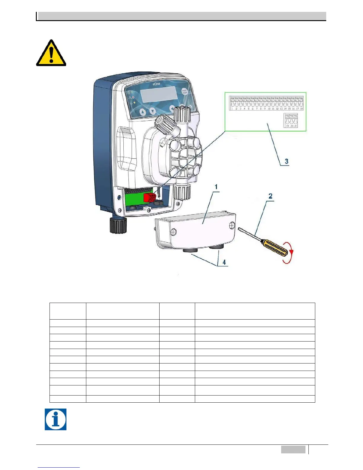
DIAGRAM OF ELECTRICAL CONNECTIONS TO PERIPHERALS
To connect the accessories and peripherals to the pump remove the front cover "1", using a flat-tip screwdriver on
the two plastic screws, to access the terminal board (see Figure 9).
The "3" terminal board features spring terminals (there are no screws) for quick connection of the cables: press with
a small screwdriver at the "carved" square pin and insert the conductor previously stripped in the corresponding terminal.
Fig. 9 Terminal Board
The connector for the pH, RX, or Cl probe is placed in the lower part of the metering pump.
N° Terminal Description N° Terminal Description
1
mA (-) Input
12
Not Connected
2
mA (+) Input
13
Not Connected
3
Meter Input (-)
14
PT100 (-) Input
4
Meter Input (+)
15
PT100 Input (+)
5
Level / Remote C. Input (-)
16
Not Connected
6
Level / Remote C.Input (+)
17
Probe (Cl) PPM (-VCL)
7
Flow Switch Input (-)
18
Probe (Cl) PPM (+VCL)
8
Flow Switch Input (+)
19
Alarm Relay (NO)
9
Output mA (-)
20
Alarm Relay (NC)
10 Output mA (+) 21 Alarm Relay (COM)
11
Not Connected

Table of Contents

Related product manuals