PISA-E11 User`s Manual 21
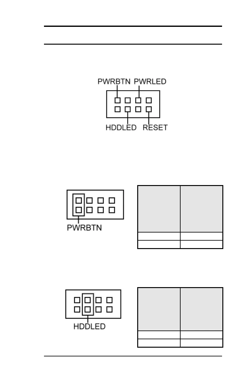
FRONT_PANEL Connector
The front panel of the case has a control panel, which provides light
indication of the computer activities and switches to change the
computer status.
ATX Power ON/OFF Button
This 2-pin connector acts as the “Power Supply On/Off Switch” on
the E11 main board. When pressed, the switch will force the Main
board to power on. When pressed again, it will force the main board
to power off.
IDE Hard Disk LED Connector
This connector connects to the hard drive activity LED on control
panel. This LED will flash when the HDD is being accessed.