Operating Instructions
Transponder-Coded Safety Switch CTS-C1-BP/BR-FLX
10
(translation of the original operating instructions) MAN20001587-01-02/23
6. Function
The device monitors the position of movable guards and can enable locking of movable guards.
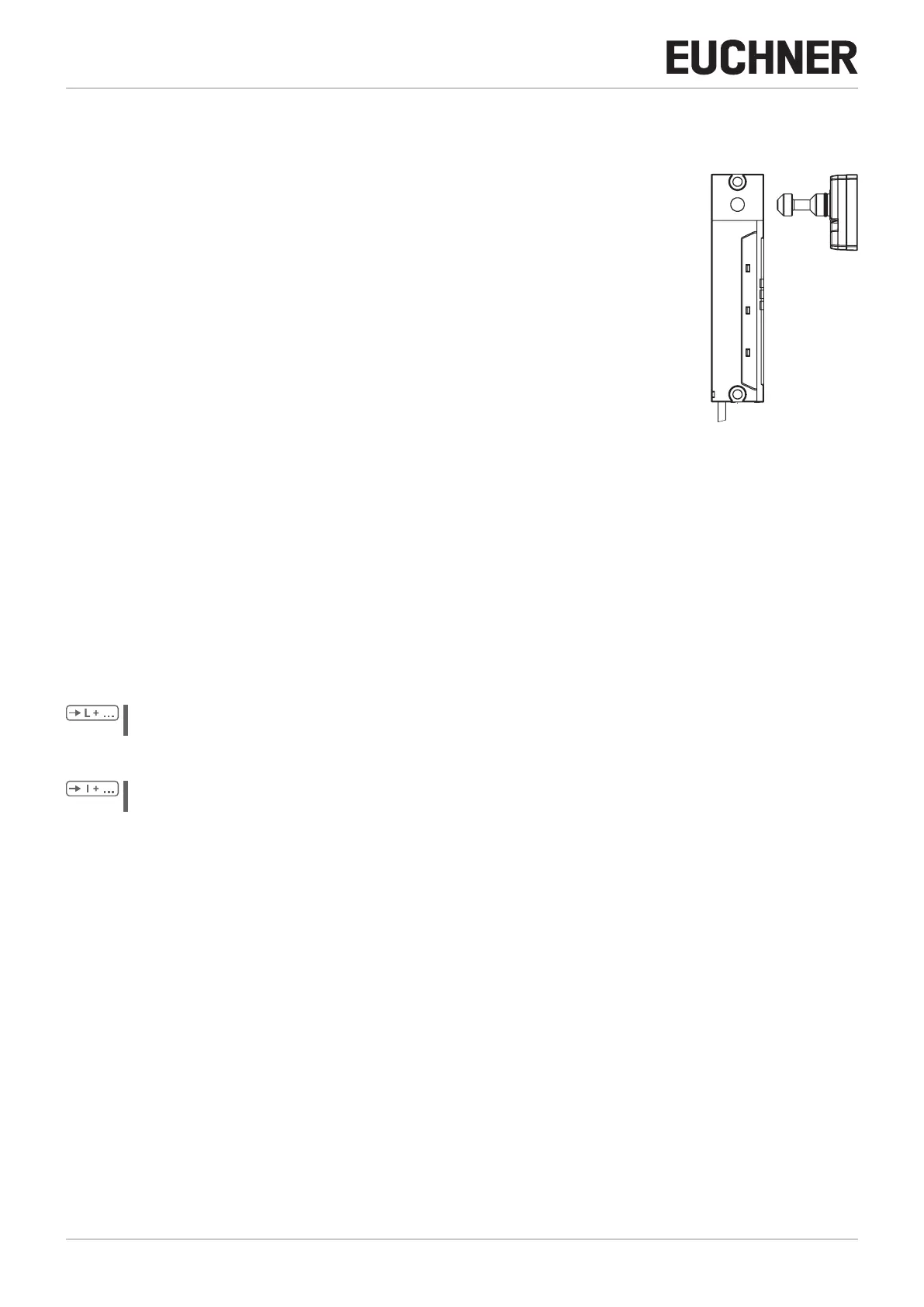
The system consists of the following components: coded actuator (transponder) and switch.
The coding level of the system depends on the conguration of the device (see chapter 13.1.
Conguring device and teaching-in actuator for the rst time on page 32).
When the guard is closed, the actuator is moved into the safety switch. When the operating
distances are reached, power is supplied to the actuator by the switch and data are transferred.
The door position1 signal OD is set if a permissible code is detected. Guard locking is activated
automatically when no voltage is present at the guard locking solenoid. The switching conditions for the safety outputs
depend on the conguration of guard lock monitoring (see chapter 6.4. Switching states on page 12).
If there is a fault in the safety switch, the safety outputs are switched off and the DIA LED illuminates or ashes red (see
chapter 15.3. Error messages on page 37). The occurrence of faults is detected at the latest on the next demand to
close the safety outputs (e.g.on starting).
6.1. Guard lock monitoring
The device is congured with the aid of the function actuator. Guard lock monitoring is switched on or off depending on the
taught-in function actuator. Further information about the possible settings is available in chapter 13.1. Conguring device
and teaching-in actuator for the rst time on page 32.
The following applies to active guard lock monitoring:
All versions feature two safe outputs for monitoring guard locking. The safety outputs FO1A and FO1B are switched
off and the guard locking signal OL is cleared when guard locking is released.
The following applies to inactive guard lock monitoring:
All versions feature two safe outputs for door position monitoring. The safety outputs FO1A and FO1B are switched
off and the door position1 signal OD is cleared when the guard is opened.
6.2. Monitoring outputs/status bits
Depending on version, the signals listed in the following are available as a status bit or at the monitoring output. The status
bits are evaluated via the BR/IO-Link Gateway. Please refer to the corresponding data sheet for further information.
6.2.1. Guard locking signal OL
The guard locking signal is present if the guard locking is active.
6.2.2. Door position1 signal OD
The door position1 signal is sent as soon as the actuator is inserted into the switch head (state: guard closed and not
locked). The signal is also present if the guard locking is active.
Switch Coded actuator