21
MAN20001587-01-02/23 (translation of the original operating instructions)
Operating Instructions
Transponder-Coded Safety Switch CTS-C1-BP/BR-FLX
EN
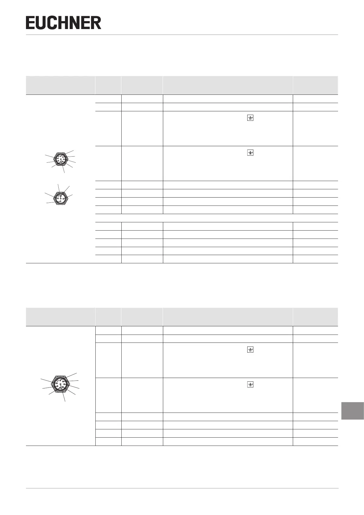
9.5. Connector assignment/terminal assignment of safety switch
CTS-…-VAB-… with plug connectors 2 x M12,
CTS-…-V05-… with connecting cable
Plug connector
(view of connection side)
Pin Designation Function
Conductor color-
ing of connecting
cable
1)
2xM12
X2.5
X1.8
X1.5
X1.6
X1.7
X1.2
X2.4
X2.1
X2.2
X1.4
X1.3
X1.1
X1.1 FI1B Enable input, channel B WH
X1.2 UB Electronics operating voltage, 24VDC BN
X1.3 FO1A
Safety output, channelA
Active guard lock monitoring:
ON, if door is closed and locked.
Inactive guard lock monitoring:
ON, if door is closed.
GN
X1.4 FO1B
Safety output, channelB
Active guard lock monitoring:
ON, if door is closed and locked.
Inactive guard lock monitoring:
ON, if door is closed.
YE
X1.5 OX1
2)
Door monitoring output 1 GY
X1.6 FI1A Enable input, channel A PK
X1.7 0VUB Electronics operating voltage, 0VDC BU
X1.8 - n.c. RD
X2.1 IMM Solenoid operating voltage, 0VDC BN
X2.2 OX2
2)
Door monitoring output 2 WH
X2.3 - n.c. BU
X2.4 IMP Solenoid operating voltage, 24VDC BK
X2.5 - n.c. GY
1) Only for standard EUCHNERconnecting cable
2) The function of the monitoring output OX is determined by the actuator taught-in. You will nd more detailed information in the data sheet 2153710 or
at www.euchner.com.
9.6. Connector assignment of safety switch
CTS-…-VSA-…
with plug connector M12, 8-pin
Plug connector
(view of connection side)
Pin Designation Function
Conductor color-
ing of connecting
cable
1)
1 x M12
8
5
6
7
2
4
3
1
1 IMP Solenoid operating voltage, 24VDC WH
2 UB Electronics operating voltage, 24VDC BN
3 FO1A
Safety output, channelA
Active guard lock monitoring:
ON, if door is closed and locked.
Inactive guard lock monitoring:
ON, if door is closed.
GN
4 FO1B
Safety output, channelB
Active guard lock monitoring:
ON, if door is closed and locked.
Inactive guard lock monitoring:
ON, if door is closed.
YE
5 OX1
2)
Door monitoring output 1 GY
6 OX2
2)
Door monitoring output 2 PK
7 0VUB Electronics operating voltage, 0VDC BU
8 IMM Solenoid operating voltage, 0VDC RD
1) Only for standard EUCHNERconnecting cable
2) The function of the monitoring output OX is determined by the actuator taught-in. You will nd more detailed information in the data sheet 2153710 or
at www.euchner.com.
 Loading...
