15
MAN20001587-01-02/23 (translation of the original operating instructions)
Operating Instructions
Transponder-Coded Safety Switch CTS-C1-BP/BR-FLX
EN
8. Mounting
CAUTION
Safety switches must not be bypassed (bridging of contacts), turned away, removed or otherwise
rendered ineffective.
Ì Observe ENISO14119:2013, section 7, for information about reducing the possibilities for bypassing
an interlocking device.
NOTICE
Risk of damage to equipment and malfunctions as a result of incorrect installation.
Ì Safety switches and actuators must not be used as an end stop.
Ì Observe EN ISO 14119:2014, sections 5.2 and 5.3, for information about mounting the safety switch
and the actuator. The following specications must be observed:
- Mounting with screws of property class 8.8 or higher.
- The minimum screw diameter is 5mm.
- Secure the xing material against loosening (e.g. by means of medium-strength positive screw
locking).
Ì Protect the switch against damage, as well as against penetrating foreign objects such as swarf,
sand and blasting shot, etc.
Ì Observe the min. door radii (see chapter 16.4.1. Dimension drawing for actuatorA-FLX-D-0.-… on page
45).
Ì Observe the maximum permissible inclination angles between switch and actuator (see Fig. 4).
Ì Observe the tightening torque for fastening the switch and the actuator (see Fig. 3):
- Actuator: 6Nm
- Switch head: 6Nm
- Switch housing: 3Nm
Ì Actuator and safety switch must be mounted such that the actuator is perpendicularly and complete-
ly inserted into the switch when the guard is closed (see Fig. 2). The guard locking function is not
assured if installation is incorrect.
Ì The locking screw of the auxiliary release must be sealed before setup, e.g. with sealing lacquer.
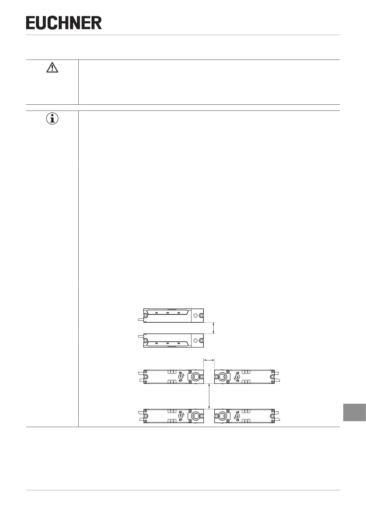
Ì When mounting several safety switches, observe the stipulated minimum distance to avoid mutual
interference.
20
20
50
 Loading...