Operating Instructions
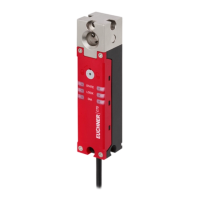
Transponder-Coded Safety Switch CTS-C1-BP/BR-FLX
2
(translation of the original operating instructions) MAN20001587-01-02/23
Contents
1. About this document ............................................................................................. 4
1.1. Scope ............................................................................................................................................ 4
1.2. Target group ..................................................................................................................................4
1.3. Key to symbols ...............................................................................................................................4
1.4. Supplementary documents ..............................................................................................................4
2. Correct use .......................................................................................................... 5
3. Description of the safety function .......................................................................... 7
3.1. With active guard lock monitoring .......................................................................................7
3.2. With inactive guard lock monitoring .....................................................................................8
4. Exclusion of liability and warranty ......................................................................... 9
5. General safety precautions ................................................................................... 9
6. Function ............................................................................................................. 10
6.1. Guard lock monitoring ...................................................................................................................10
6.2. Monitoring outputs/status bits .......................................................................................................10
6.2.1. Guard locking signal OL .................................................................................................10
6.2.2. Door position1 signal OD ...............................................................................................10
6.2.3. Door position2 signal OT ...............................................................................................11
6.2.4. Diagnostic signal OI .......................................................................................................11
6.2.5. Escape release signal OER ............................................................................................11
6.2.6. Status signal OM ............................................................................................................ 11
6.2.7. Locking element signal OLS ............................................................................................ 11
6.2.8. Communication connection C .......................................................................................... 11
6.3. Guard locking ...............................................................................................................................11
6.4. Switching states ...........................................................................................................................12
7. Manual release ................................................................................................... 13
7.1. Auxiliary release............................................................................................................................13
7.1.1. Actuating auxiliary release ..............................................................................................13
7.2. Escape release .............................................................................................................................14
7.2.1. Actuating escape release ...............................................................................................14
8. Mounting ............................................................................................................ 15
9. Electrical connection .......................................................................................... 18
9.1. Notes about .........................................................................................................................19
9.2. Safety in case of faults .................................................................................................................. 19
9.3. Fuse protection for power supply ...................................................................................................19
9.4. Requirements for connecting cables ...............................................................................................20
9.5. Connector assignment/terminal assignment of safety switch
CTS-…-VAB-… with plug connectors 2 x M12,
CTS-…-V05-… with connecting cable .............................................................................................21
9.6. Connector assignment of safety switch
CTS-…-VSA-…
with plug connector M12, 8-pin ................................................................................... 21
9.7. Notes on operation with safe control systems .................................................................................22