The Harmonizer
®
Programmer’s Manual
© 1999-2008 Eventide, Inc. Page 29 of 97 Release 1.3
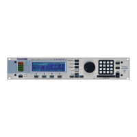
• Here we see the four specifiers for the meter module. The
meter module monitors a control signal output and displays its
value in what looks like an old-school VU meter.
• The minimum specifier sets the lowest value that will be
displayed, while the maximum specifier sets the highest. The
name specifier sets the description of the meter, and the tag
specifier sets the description on its SOFT KEY (if it has one).
All of these items are selected by you, the program’s
creator, at its inception. The user can’t change any of this stuff.
There is one other type of specifier that we’ve deliberately ignored: the sort that controls “repeating
fields." This sort of specifier can’t be altered from the Vsigfile
Specifier
Display and is discussed in a section all
to itself below.
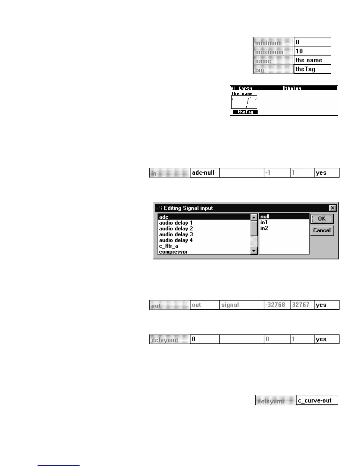
Audio Inputs
Returning to the Vsigfile
Specifier
Display window for the delay module that we started out with, the next row
after the specifier row displays the audio inputs.
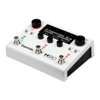
Double clicking on the MODULE
column calls up yet another
window: the “Editing Signal Input”
window. Here you can select
among all of the possible audio
outputs in your patch.
The output you select will be connected to the input you double clicked on to call up the Editing Signal input
window. If connecting things this way works for you, great, but most folks find it easier to click and
drag in the normal Vsigfile display.
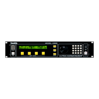
Audio Outputs
The next row displays the audio output. Well, actually it just tells you that it exists. This row is mainly
useful if you want to “hide” the audio output.
Control Inputs
The next row on the other hand, is very useful. It describes the control input for the module. The type
column tells you what the control input is for (in this case, ‘delayamt’ controls the amount of delay). If no
control output is connected to this control input
(as is the case here), the MODULE column allows you to set the
delay amount just as you would in the
PARAMETER area on the Harmonizer. The value you enter is
constrained by the min and max columns (‘0’ and ‘1’ in this case).
If a control output is connected to this control input (as is the case shown to
the right)
, its module name and output will be displayed.