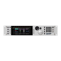
The Harmonizer
®
Programmer’s Manual
© 1999-2008 Eventide, Inc. Page 68 of 97 Release 1.3
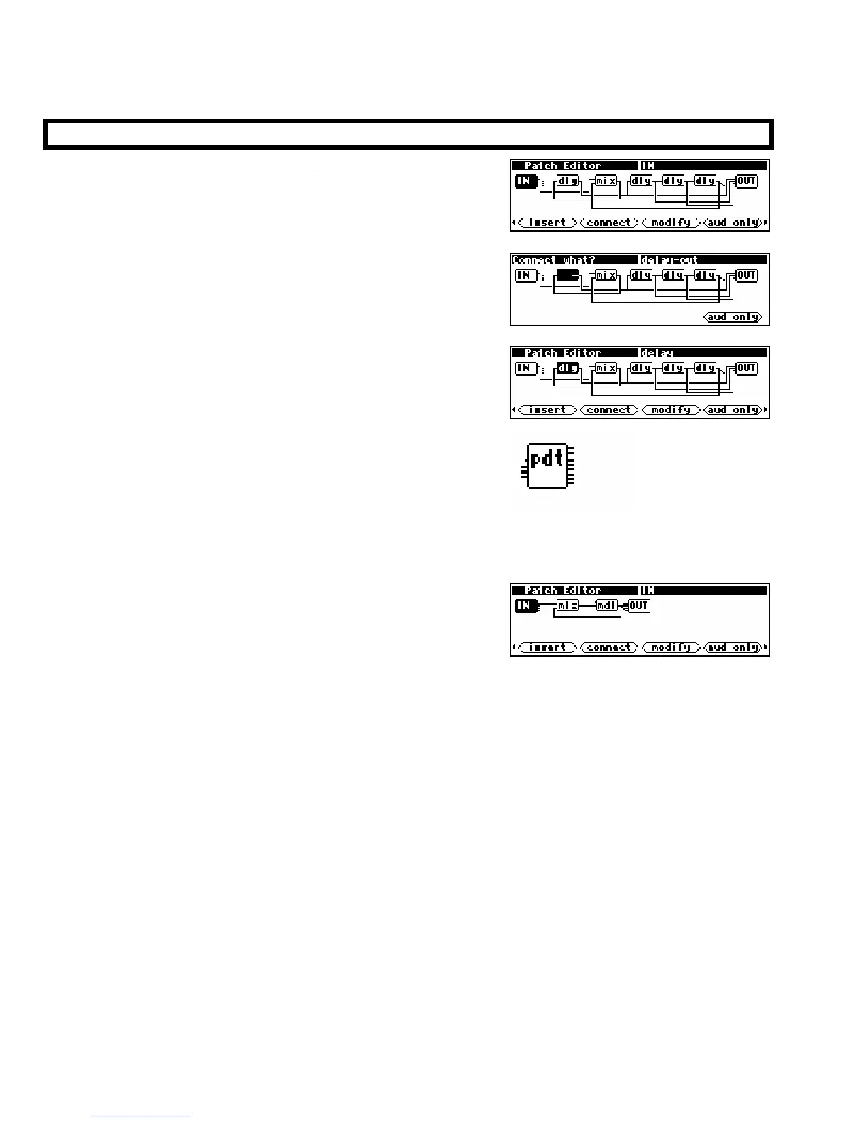
THE PATCH EDITOR AREA DISPLAY
When the PARAMETER key is pressed and held, the Harmonizer
presents a Patch Editor area display of the current program along
with a selection of
SOFT KEYS. This is the default Patch Editor
area screen. Unlike the other areas in the Harmonizer, the top
line of the screen is used for “special purposes."
The left half of the top line is used as a question field when the
<connect> or <unplug> SOFT KEY is used.
The right half of the top line shows the name of the currently
selected module (except during <connect> or <unplug>
operations when it shows the currently selected input or output).
A block diagram of the program takes up most of the display.
As mentioned before, a program consists of a series of modules.
Each module is shown on the display as a block with lines
indicating its inputs and outputs. Inputs are on the left side of a
module while outputs are on the right side. Each module is shown with a three-character (or less)
abbreviation of its function name.
→ See the Modules Section of the Vsigfile Help System for a list of all modules.
The example screen to the right shows four modules and is
shown in the default “audio only” mode. This means that the
only modules and signals shown are audio paths and modules
that work with audio. The modules shown in the example are:
IN audio from the DSP’s inputs (only one is being used)
mix a two-input mixer
mdl “modulate-able” delay
OUT audio to the DSP’s four outputs
As shown, the IN module’s output 1 is connected to one of the inputs of the mixer. The other
mixer input comes from the output of the “modulate-able” delay. The mixer feeds the
input of the delay. The delay output may be seen to drive five module inputs: the mixer input
and all four of the OUT module’s
inputs.