HDSD9545DLY - PRO Profanity Bypass Delay Manual
CONTENTS Revision 1.3.7 iii
4.2.1. Changing the Fuses ..................................................................................................... 4-3
4.2.2. JUMPERS .................................................................................................................... 4-4
4.2.2.1. Configuring the Unit for a DARS Reference
(DARS reference not implemented at the time of writing) ............................. 4-4
4.2.2.2. Configuring the Module for Firmware Upgrades
using the Serial Port Method ......................................................................... 4-4
4.3. UPGRADING FIRMWARE ...................................................................................................... 4-4
4.3.1. Upgrading the Firmware using FTP ............................................................................. 4-5
4.3.1.1. Step 1 – Determine the IP Addresses ........................................................... 4-5
4.3.1.2. Step 2 – Establishing a Valid Network Connection ....................................... 4-6
4.3.1.3. Step 3 – Upgrading the Application Code ..................................................... 4-7
4.3.1.4. Step 4 – Completing the Upgrade ................................................................. 4-8
4.3.2. Upgrading the Firmware using RS-232 Serial Cable ................................................... 4-8
4.3.2.1. Step 1 – Setup............................................................................................... 4-8
4.3.2.2. Step 2 – Invoke Upload Mode from the Terminal Program ........................... 4-9
4.3.2.3. Step 3 – Uploading the New Firmware.......................................................... 4-9
4.3.2.4. Step 4 – Completing the Upgrade ............................................................... 4-10
Figures
Figure 1-1: Standard Delay Unit Block Diagram ...................................................................................1-2
Figure 1-2: Delay Unit with HD40 option (Embedded Audio Mode) Block Diagram.............................. 1-2
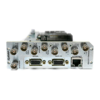
Figure 2-1: Rear Panel Layout .............................................................................................................. 2-1
Figure 2-2: General Purpose I/O Schematic ......................................................................................... 2-9
Figure 2-3: Powering the General Purpose Input Opto-Isolators from the HDSD9545DLY-PRO....... 2-10
Figure 2-4: Powering the General Purpose Input Opto-Isolators from an External Power Supply...... 2-10
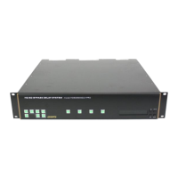
Figure 3-1: Front Panel Layout.............................................................................................................. 3-1
Figure 3-2: Operational Overview ......................................................................................................... 3-3
Figure 3-3: Overview of the Setup Menu............................................................................................... 3-4
Figure 3-4: Transition Activation Example............................................................................................. 3-9
Tables
Table 2-1: Remote CTL Port Pin Definitions ......................................................................................... 2-3
Table 2-2: GPI/O Port Pin Definitions.................................................................................................... 2-4
Table 2-3: Video Input Formats............................................................................................................. 2-5
Table 2-4. Standard RJ45 Wiring Color Codes.....................................................................................2-7