XRF1/XRF1A 16x16 RF Router Manual
XRF1 - 2-2 Revision 1.2 INSTALLATION
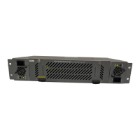
Power requirements are 115 or 230 volts AC at 50 or 60 Hz. The router has universal power supply(s) that
automatically sense input voltage. Power should be applied by connecting a 3-wire grounding type power
supply cord to the power entry module on the rear panel. The power cord should be minimum 18 AWG
wire size; type SVT marked VW-1, maximum 2.5 m in length.
The IEC 320 power entry module combines a standard power inlet connector, two 5 x 20 mm fuse holders
and an EMI line filter.
2.3.1. Changing the Fuses
The fuse holder is located inside the power entry module. To change the fuses, remove the fuse holder
from the power entry module using a small screwdriver. The fuse holder contains two fuses, one for the
line and one for the neutral side of the mains connection. Remove the blown fuse and replace it with a
fuse of the correct value. Replacement fuse type: T1AL250V, slow blow, 1A, 250VAC (non LNB),
T4AL250V, slow blow, 4A, 250VAC (LNB option).
!
Never replace with a fuse of greater value.
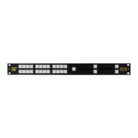
2.3.2. Serial Port Breakout Cable Control / Upgrade Connection
This 15 pin female D connector provides an RS-232/RS-422 serial interface used for external serial remote
control. A breakout cable is provided with the router to separate to three 9 pin female D connectors. The
cable labelled ‘UPGRADE1’ is a RS232 connection to the frame controller (FC) CPU for performing
configuration and status monitoring in a terminal session on a PC and also upgrading the FC CPU
firmware. The cable labeled ‘UPGRADE2’ is a RS232 connection that allows upgrading of the micro-
controller. The cable labeled ‘CONTROL’ is a RS232/RS422 connection used to control the router via
Evertz Router Control serial control protocol (please contact Evertz sales or service for details on this
protocol). The Main Menu / Serial Port Configuration menu of the FC configuration port (UPGRADE1) is
used to configure the serial port for external control.
Refer to Table 2-1 and Table 2-2 for the pinout of these cables in RS232 or RS422 modes.
Pin # Name Description
1
GND Chassis ground
2
TxD RS-232 Transmit Output
3
RxD RS-232 Receive Input
4
5
Sig Gnd RS-232 Signal Ground
6
7
RTS RS-232 RTS Input
8
CTS RS-232 CTS Output
9
Table 2-1: Router RS-232 Port Pin Definitions