XRF1/XRF1A 16x16 RF Router Manual
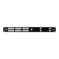
XRF1 - 4-16 Revision 1.2 FRONT PANEL INTERFACE
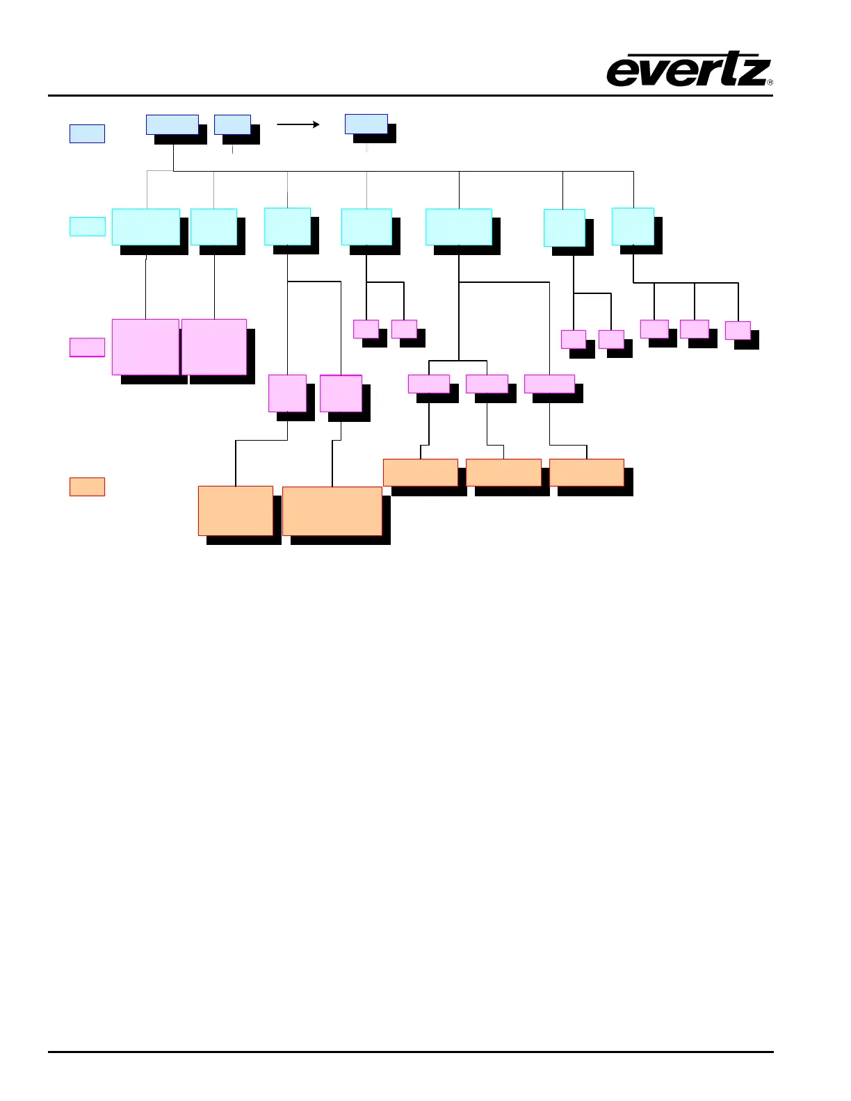
OUTPUT
LEVEL
GAIN
MODE
SQUELCH
RF
THRESHHOLD
LNB
POWER
Statuses current
Input Level
-5 to -70 dBm
Statuses current
Output Level
-20 to -50 dBm
AGC
MODE
MANUAL
GAIN
MODE
OFFON
UPPER LOWER SQUELCH
Displays -5dBm (allows
parameter setting in 1dBm
increments to -30dBm)
Displays -70dBm (allows
parameter setting in 1dBm
increments to -31dBm)
Displays -70dBm (allows
parameter setting in 1dBm
increments to -50dBm)
SETS OUTPUT LEVEL
Displays -20dBm (allows
parameter setting in 1dBm
increments to -50dBm)
SETS OUTPUT VS. INPUT GAIN
DIFFERENCE
Displays 0dB (allows parameter
setting in 1dB increments from -
15dB to -16dB)
LEVEL 1
LEVEL 2
LEVEL 3
LEVEL 4
INPUT 16
….. …..
LNB
RESET
+13V
OFF
+18V
NO
YES
ALL INPUTS INPUT 1
INPUT LEVEL
( ind. ch )
Figure 4-3: Configuration Menus Structure per Input Channel