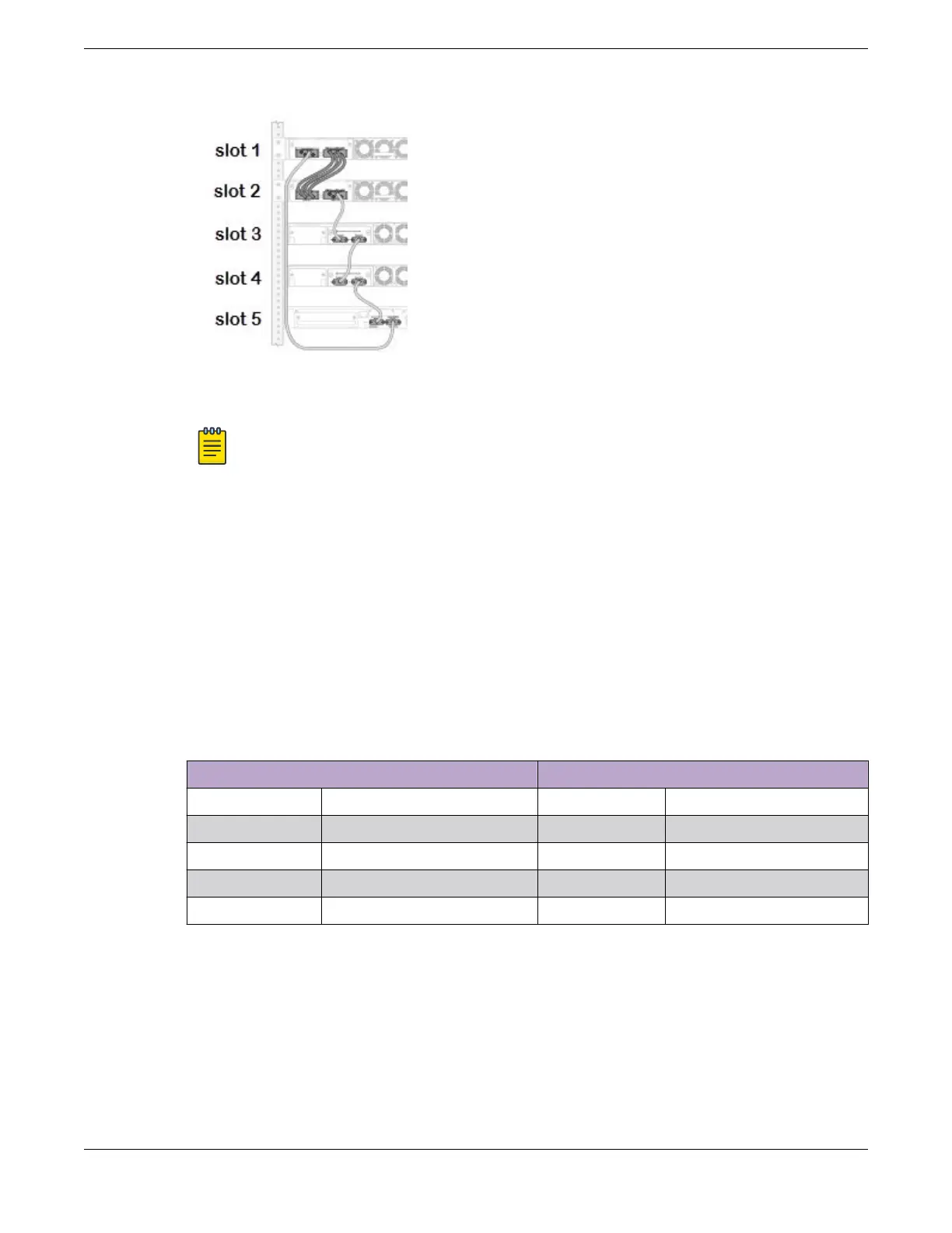
Figure 40: Combining Stacking Port Types: Example
Note
The figure is intended to show cable connections between switches. Details of the switches
themselves, such as the location of the stacking ports and fan modules, might dier from
those of the switches that actually would be used.
The following cables are used to make the stacking connections:
• QSFP+ cable connecting the two switches at the top (slot 1 and slot 2)
• SFP+ cable connecting the switch in slot 2 with the switch in slot 3
• SFP+ cable connecting the switch in slot 3 with the switch in slot 4
• SFP+ cable connecting the switch in slot 4 with the switch in slot 5
• SFP+ cable connecting the switch in slot 5 with the switch in slot 1
Table 18 lists the recommended order for connecting the stacking ports in this example.
Table 18: Combining Stacking Port Types: Connections
Connect this slot and port . . . . . . To this slot and port
Slot 1 Stack Port 2 Slot 2 Stack Port 1
Slot 2 Stack Port 2 Slot 3 Stack Port 1
Slot 3 Stack Port 2 Slot 4 Stack Port 1
Slot 4 Stack Port 2 Slot 5 Stack Port 1
Slot 5 Stack Port 2 Slot 1 Stack Port 1
Using SummitStack-V160 Stacking
A stacking rate of 160 Gbps can be achieved using certain configurations of Extreme Networks
switches. For example, an X460-G2 switch can be connected to an X670-G2-48x-4q switch through
40-Gbps stacking connections that provide 160 Gbps full-duplex bandwidth. This connection is
performed using the VIM-2q module in the X460-G2 switch and the QSFP+ ports on the X670-
G2-48x-4q switch.
Building Stacks
Connecting the Switches to Form the Stack Ring
ExtremeSwitching 5420 Series Hardware Installation Guide 67
 Loading...

