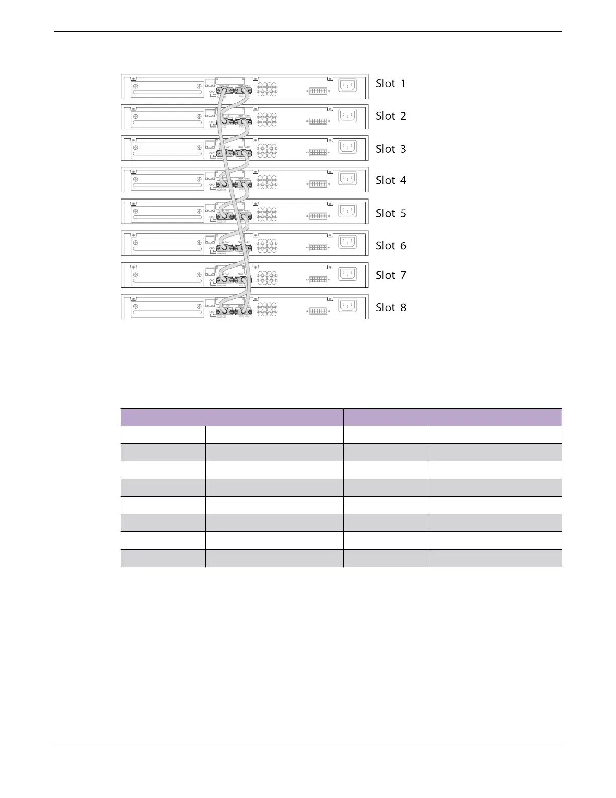
Figure 42: SummitStack Cable Connections Using Eight Switches with Integrated
SummitStack Ports
Table 20 lists the recommended order for connecting the stacking ports in this example.
Table 20: Basic Stack with Eight Switches: Connections
Connect this slot and port . . . . . . To this slot and port
Slot 1 Stack Port 2 Slot 2 Stack Port 1
Slot 2 Stack Port 2 Slot 3 Stack Port 1
Slot 3 Stack Port 2 Slot 4 Stack Port 1
Slot 4 Stack Port 2 Slot 5 Stack Port 1
Slot 5 Stack Port 2 Slot 6 Stack Port 1
Slot 6 Stack Port 2 Slot 7 Stack Port 1
Slot 7 Stack Port 2 Slot 8 Stack Port 1
Slot 8 Stack Port 2 Slot 1 Stack Port 1
Example: Stack with VIM1-SummitStack Modules
Figure 43 shows an example of a four-switch stack that combines two dierent switch models: two of
each model; four switches in all. For the first switch model, the stacking ports are on installed VIM1-
SummitStack modules. For the second switch model, the stacking ports are on installed SummitStack
stacking modules. The recommended order for connecting the stacking ports is the same as for the
example in Example: Basic Stack with Eight Switches on page 68.
Building Stacks
Connecting the Switches to Form the Stack Ring
ExtremeSwitching 5420 Series Hardware Installation Guide 69
 Loading...

