Mt 880/870/En/Rev. 002/05/98 * 901.882.002
BEISSBARTH MT 870 / MT 880
4-5
Special flanges for wheels with no centre hole
For all closed-centre wheels with either 3, 4 or 5 stud holes, and also for all wheels with an unma-
chined centre hole, UNI flanges are used to clamp the wheels to the balancing machine.
In order to keep clamping errors to a minimum, the tyre valve should always be at the bottom when
clamping the wheel to the flange and fitting it to the vehicle. Always tighten the nut nearest to the
tyre valve first, then the remaining nuts in a pattern which proceeds across the centre of the wheel
to the other side each time. After completion of balancing, fit the wheel to the vehicle by following
precisely the same procedure.
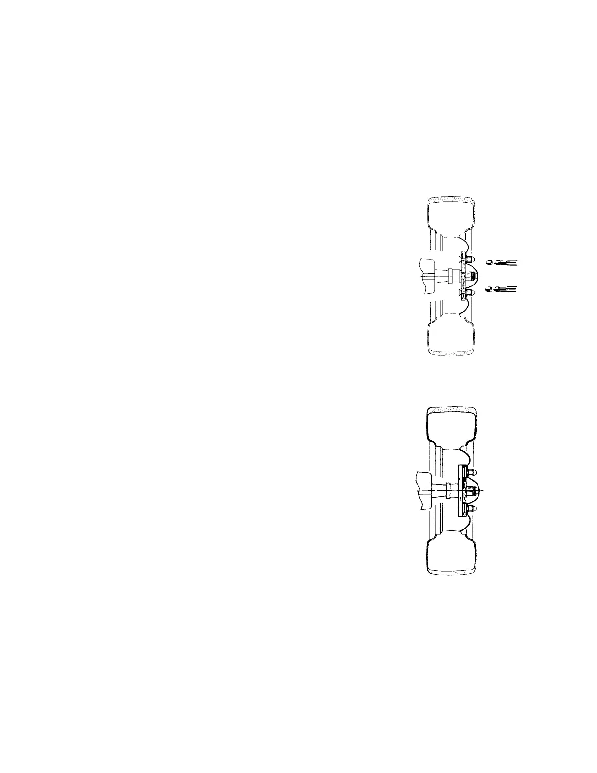
9. Centring and securing the wheel with insert pins and double-
cone nuts or quick-clamping cones.
Select the correct hole pitch circle at the hole centring plate on the
flange and insert the required number of pins. Secure the insert pins
by tightening the knurled nuts at the rear. Push the wheel’s stud holes
carefully over the insert pins until it touches the face of the flange.
Use a 22 mm box wrench to tighten the double-cone nuts on the ins-
ert pins or the quick-clamping cones (see Fig. 9).
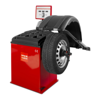
10. Centring and securing the wheel with sliding pins and double-
cone nuts or quick-clamping cones.
Insert the correct number of sliding pins into the guides on the flan-
ge and adjust them to the correct hole pitch circle. The sliding pins
are located by ball detents at the selected hole pitch circle. The wheel
is attached to the flange as described in Fig. 9 (see Fig. 10).
11. Centring and securing the wheel with continuously adjustable
swivel pins and double-cone nuts or quick-clamping cones:
Unscrew the swivel pins with the T-pattern Allen key and, as neces-
sary, insert the central disc for 3-hole or the combination disc for 4-
and 5-hole wheels into the cutout on the flange. Attach the neces-
sary
swivel pins loosely at first, according to the numbers stamped on
them. To adjust the flange accurately to the desired hole pitch circle,
measure the stud holes on the wheel with sliding calipers and trans-
fer the measurement to the swivel pins. Tighten the swivel pins with
the Allen key. Attach the wheel to the flange as described in Item 9
(see Fig. 10).
Fig. 9
Fig. 10