16
Maintenance. (Sensor checking)
Self-test
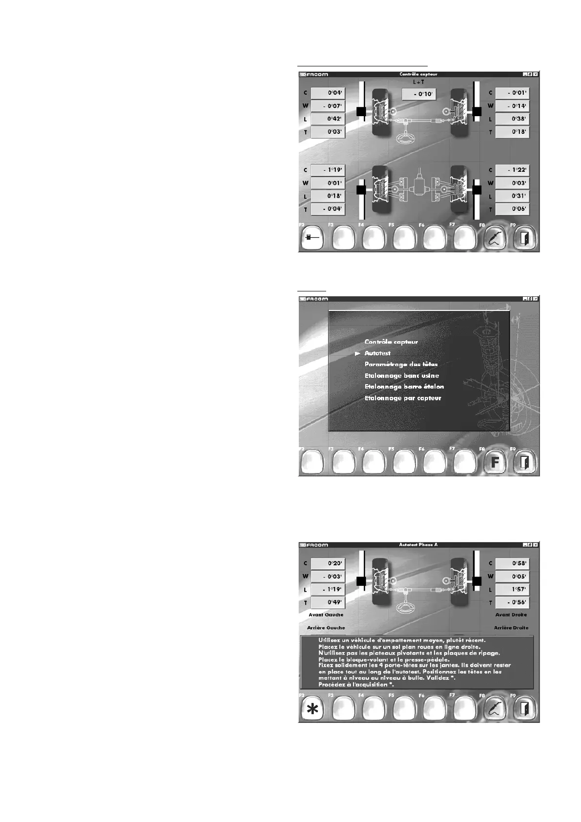
8.8.1 Sensor verification
Validate using the Enter key.
This screen lets you verify the accuracy of L and T sensors. With
the heads in position on the vehicle, the algebraic sum of sensors
L and T must be near zero.
Formula: (T1+T2-L1-L2+L3+L4-T3-T4=0).
All sensor readouts must be significant.
- A reading of ± 136° 31’ indicates sensor saturation.
- A reading of ± 136° 21’ indicates beam interruption.
- A reading of ± 136° 30’ indicates a weak infrared signal.
"F2" "
Measuring head selection
"
"F8" "
Maintenance
"
"F9" "
Return to function menu
"
8.8.2 Self-test
Description
The self-test allows the user to check the operating status of a
measuring head if for example the head has been dropped and
there is a doubt as to the accuracy of subsequent vehicle
measurements. The test procedure is straightforward and no ex-
tra accessories are required.
The heads are mounted normally on the vehicle’s wheels in the
order specified on the screen.
The validity of the test is based on the assumption that only one
head is giving “
wrong
” readings. If one sensor is considered to
be “
wrong
”, the two heads compared will be declared as doubtful
except for the level sensor (W) which reads out directly.
Using F8, select the “
Other Functions
” menu, followed by line
“
Maintenance
”. Confirm this choice by pressing Enter. The next
screen will be displayed.
- Select the “
Self-test
” option.
- Confirm the selection by pressing Enter.
- The next screen will be displayed.
Follow the instructions on the screen.
Important: Level the heads with a high-precision spirit level
(see spare parts references). Do not use the electronic head
level system.
NB: Carry out all procedures with extreme care.
- Acknowledge the message.
- Confirm data acquisition.
- The next screen will be displayed.