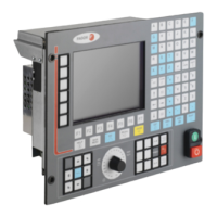
Installation manual
CNC 8035
CONCEPTS
feedback system
5.
(SOFT M: V15.3X)
(S
OFT T: V16.3X)
·197·
5.4 feedback system
The various feedback inputs available at the CNC admit sinusoidal and squarewave differential
signals from feedback systems. The following axis machine parameters indicate the type of
feedback system and the resolution used for each axis.
• When using linear feedback devices.
• When using rotary encoders.
Next, the feedback counting speed (frequency) limitation is described as well as how to set these
machine parameters for the axes.
PITCH (P7) Pitch of the linear encoder being used.
NPULSES (P8) = 0
DIFFBACK (P9) Indicates whether the feedback device uses differential signals (double
ended) or not.
SINMAGNI (P10) Feedback multiplying factor applied by the CNC.
FBACKAL (P11) Feedback alarm (only with differential signals).
PITCH (P7) On rotary axes, it sets the degrees per turn of the encoder.
On linear axes, it sets the leadscrew pitch.
NPULSES (P8) Number of pulses (lines) per encoder turn.
DIFFBACK (P9) Indicates whether the feedback device uses differential signals (double
ended) or not.
SINMAGNI (P10) Feedback multiplying factor applied by the CNC.
FBACKAL (P11) Feedback alarm (only with differential signals).

 Loading...