Installation manual
CNC 8035
PLC RESOURCES
Counters
6.
(SOFT M: V15.3X)
(S
OFT T: V16.3X)
·281·
6.6 Counters
They are elements capable of counting up or down a preset amount of events. They do not have
image values and are represented by the letter C, followed by the counter number which it is required
to reference, for example C1, C25, C102, etc.
The counter's count is stored in a 32-bit variable. Consequently, its value will be in the ±2147483647
range.
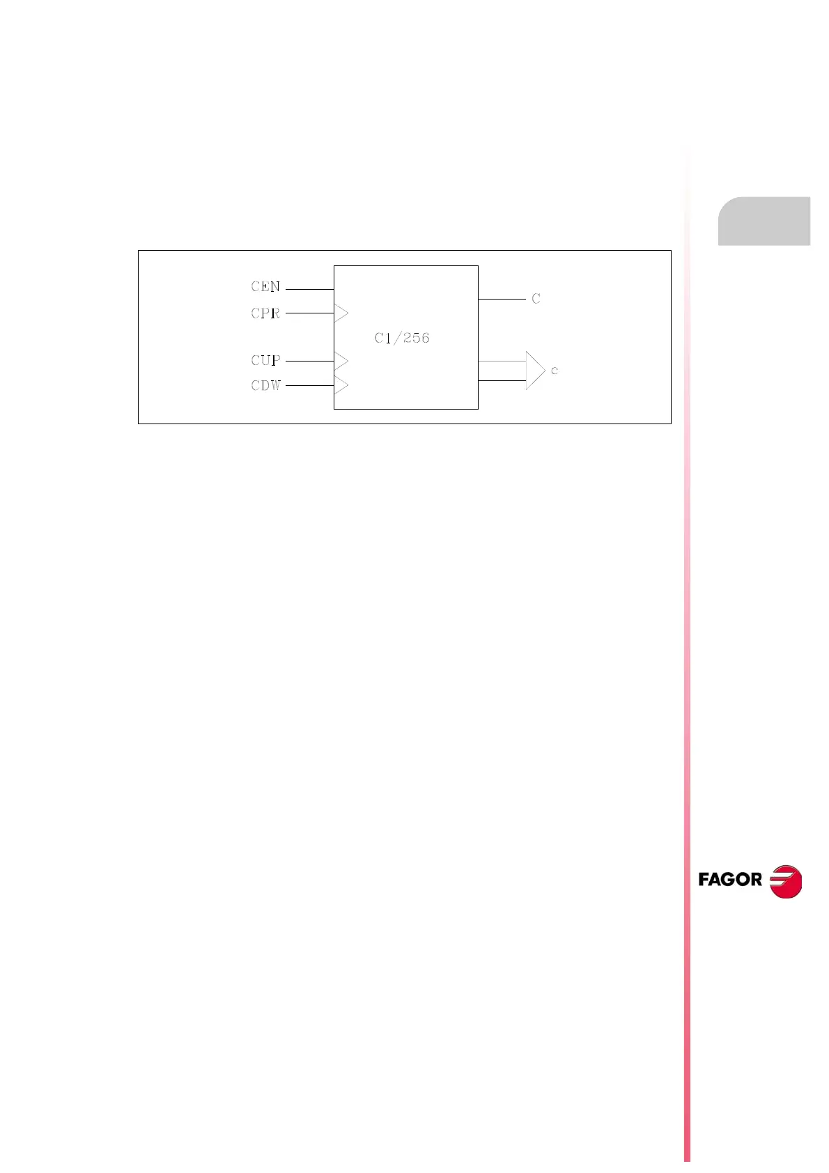
The PLC has 256 counter, each of which has the C status output and CUP, CDW, CEN and CPR
inputs. It is also possible to consult the count value at any time.
Feedback input (CUP)
This input allows the counter count to be increased in a unit every time a leading edge is produced
in it. It is referred to by the letters CUP followed by the counter number, for example: CUP 1, CUP
25, CUP 102, etc.
Example:
I2 = CUP 10 Every time a leading edge is produced at input I2 the counter count C10 will
be increased.
Count-down input (CDW)
This input allows the counter count to be decreased in a unit every time a leading edge is produced
in it. It is referred to by the letters CDW followed by the counter number, for example CDW 1, CDW
25, CDW 102, etc.
Example:
I3 = CDW 20 Every time a leading edge is produced at input I3 the counter count C20 will
be decreased.