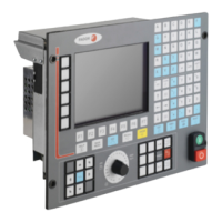
Installation manual
CNC 8035
5.
CONCEPTS
Reference systems
(SOFT M: V15.3X)
(S
OFT T: V16.3X)
·218·
5.6.3 Setting on systems with distance-coded feedback
Offset adjustment
The offset of the linear encoder must be adjusted on one axis at a time, preferably, following this
procedure:
1. Set the following a.m.p:
REFDIREC (P33) Homing direction.
"REFEED2" (P35) Homing feedrate.
2. Verify that the value allocated to a.m.p. REFPULSE (P32) (type of marker pulse of the feedback
system) is correct.
To do this, set a.m.p. DECINPUT (P31) = NO and a.m.p. I0TYPE (P52) = 0. Then perform a home
search.
If assumed immediately, change a.m.p. REFPULSE (P32) and check again.
3. Set a.m.p. I0TYPE (P52) = 1 and ABSOFF (P53) = 0.
4. Once in JOG mode and after positioning the axis in the proper area, home the axis. The new
position value displayed by the CNC is the distance from the current point to the origin of the
linear encoder.
5. Perform several consecutive home searches and observe the CNC display during the whole
process.
The counting must be continuous. If it is not, if jerky, set a.m.p. I0TYPE (P52) = 2 and repeat
steps 4 and 5.
6. Move the axis up to the Machine Reference Zero or up to a point whose position with respect
to Machine Reference Zero is already known and observe the position value displayed by the
CNC. This value is the distance from the current point to the origin of the linear encoder.
7. The value to be assigned to a.m.p. ABSOFF (P53) must be calculated with the following formula:
ABSOFF (P53) = CNC reading - Machine coordinate.
Example:
If the point whose position is already known is located 230 mm from Machine Reference Zero
and the CNC shows -423.5 mm as the position for this point, the linear encoder offset will be:
ABSOFF (P53) = -423,5 - 230 = -653.5 mm.
8. After allocating this new value, press SHIFT + RESET or turn the CNC off and back on in order
for the CNC to assume this new value.
9. Home the axis again in order for it to assume the new correct reference values.
Considerations
If the axis is positioned beyond the software limits "LIMIT+" (P5) and "LIMIT-" (P6), it must be brought
back into the work area (within those limits) and on the proper side for referencing (home searching).
When using distance-coded linear encoders, home switches are no longer necessary.
However, home switches may be used as travel limits during home search.
If while homing, the home switch is pressed, the axis will reverse its movement and it will keep
searching home in the opposite direction.
Distance-coded Fagor linear encoders have negative coded marker pulses (Io).
Do not mistake the type of pulse provided by the feedback system with the value to be assigned
to a.m.p. REFPULSE (P32).
This parameter must indicate the type of active flank (leading or trailing edge), positive or
negative of the reference mark (Io) used by the CNC.
If while homing an axis, its corresponding DECEL* signal is set high, the axis will reverse movement
and the home search will be carried out in the opposite direction.

 Loading...