Installation manual
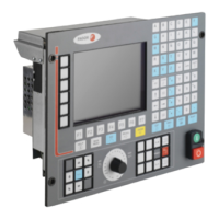
CNC 8035
CONCEPTS
Digital CAN servo
5.
(SOFT M: V15.3X)
(S
OFT T: V16.3X)
·239·
5.11 Digital CAN servo
G.m.p. CANSPEED (P169) may be used to set the CAN communication speed.
5.11.1 Communications channel
The data exchange between the CNC and the drives takes place in each position loop.
The more data to be transmitted, the more overloaded the transmission will be. These registers
should be limited leaving only the ones absolutely necessary after the setup.
On the other hand, there is data that MUST be transmitted at each position loop (velocity commands,
feedback, etc.) and other information that could be transmitted in several loops (monitoring, etc.).
Since the CNC must know the priority for those transmissions, from now on, we will use the terms
"cyclic channel" and "service channel" to refer to each of them.
Cyclic channel (fast channel)
Data transmitted at each position loop (velocity commands, feedback, etc.).
At every loop time, the CNC transmits to the drive through this channel the World Control (Speed
Enable, Drive Enable, Homing Enable, bit handshake) and the velocity command. The drive
transmits to the CNC the Word Status and the position value. The transmitted data depends on
a.m.p. DRIBUSLE (P63).
The type of data to be transmitted (basically variables) must be indicated. The data to be sent to
the drives must be placed in certain particular registers of the PLC and the data to be read from
the drives is received in other registers of the PLC.
The registers to be used and the data to be transmitted (basically variable) are defined by machine
parameters of the PLC. Use SRR700 (P28) through SRR739 (P67) parameters to transmit read-
only variables. Use SWR800 (P68) through SWR819 (P87) parameters to transmit write variables.
The number of variables defined in this channel is limited depending on the number of axes, the
sampling period and the transmission speed. A data overflow causes an error at the CNC.
Service channel (slow channel)
Data to be transmitted in several position loops (monitoring, etc.).
The service channel can only be accessed through a high-level block of a part-program, a PLC
channel or a user channel.
CAN communication requires a drive version V7.02 or later.

 Loading...