Installation manual
CNC 8035
6.
PLC RESOURCES
Counters
(SOFT M: V15.3X)
(S
OFT T: V16.3X)
·282·
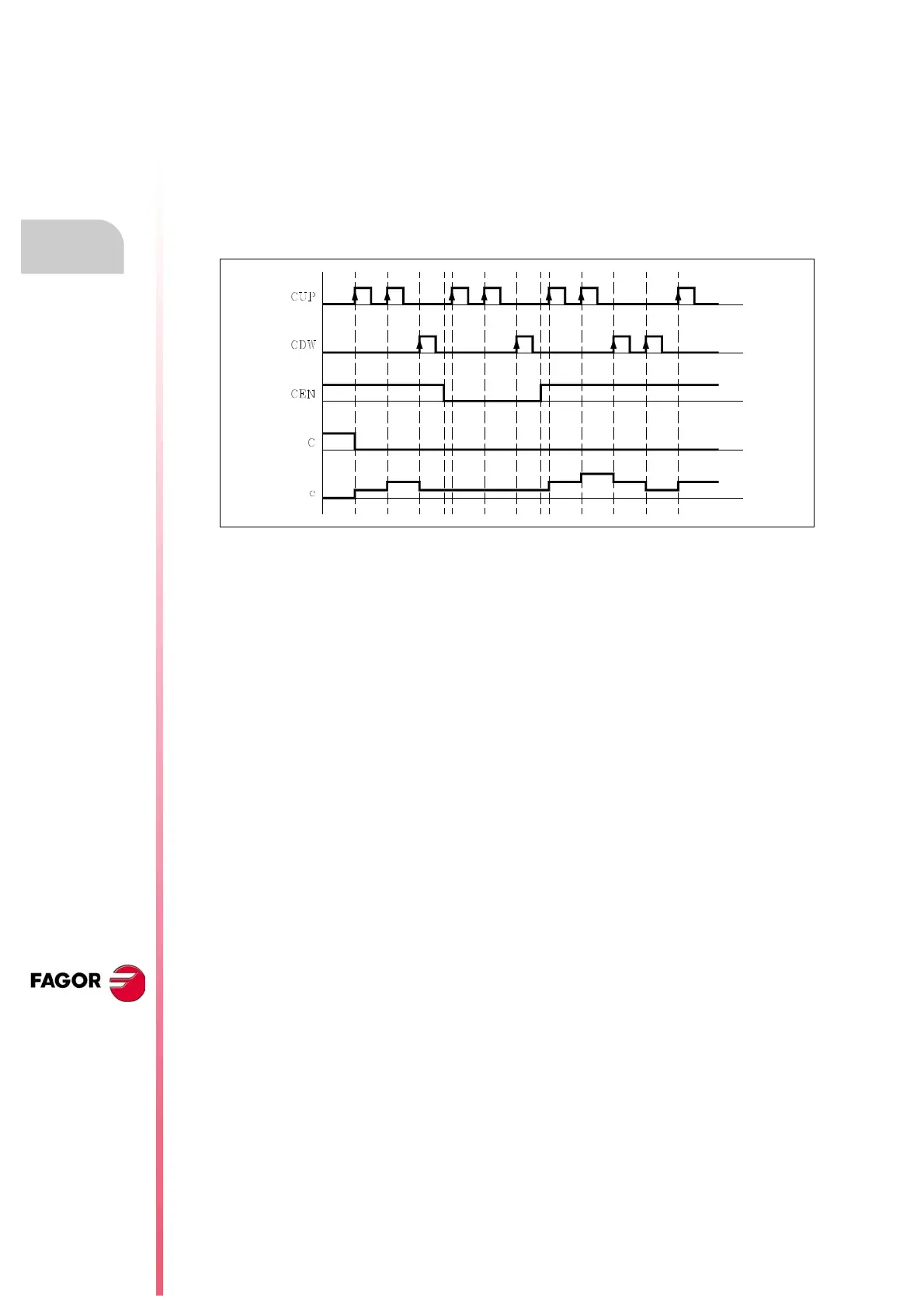
Enable input (CEN)
This input allows the internal counter count to be stopped. It is referred to by the letters CEN followed
by the counter number, for example: CEN 1, CEN 25, CEN 102, etc.
In order to be able to modify the internal count by means of the inputs CUP and CDW this input must
be at logic level “1”. By default and every time a counter is activated the PLC will assign this input
a logic level of “1”.
If CEN = 0 is selected the PLC stops the counter count, ignoring the inputs CUP and CDW until this
input allows it (CEN = 1).
Example:
I10 = CEN 12 Input I10 controls the enable input of counter C12.
Preset input (CPR)
This input allows the counter to be preset with the desired value. It is referred to by the letters CPR
followed by the number of the counter which is required to reference and the value to be assigned
to the counter count.
For example CPR 1 100, CPR 25 224, CPR 102 0, CPR 200 500, etc.
The value of the count can be indicated by means of a numerical value or by assigning to it the
internal value of an R register.
CPR 20 100 Presets the C20 counter to a value of 100.
CPR 22 R200 Presets the C22 counter with the value of the Register R200 when the
instruction is executed.
The counter is preset with the indicated value with an up-flank at the CPR input.
Status output (C)
This output indicates the logic status of the counter. It is referred to by the letter "C" followed by the
counter number, for example: C1, C25, C102, etc.
The logic status of the counter will be C=1 when its count value is "0" and C=0 if otherwise.