Installation manual
CNC 8035
CONCEPTS
Axis adjustment
5.
(SOFT M: V15.3X)
(S
OFT T: V16.3X)
·211·
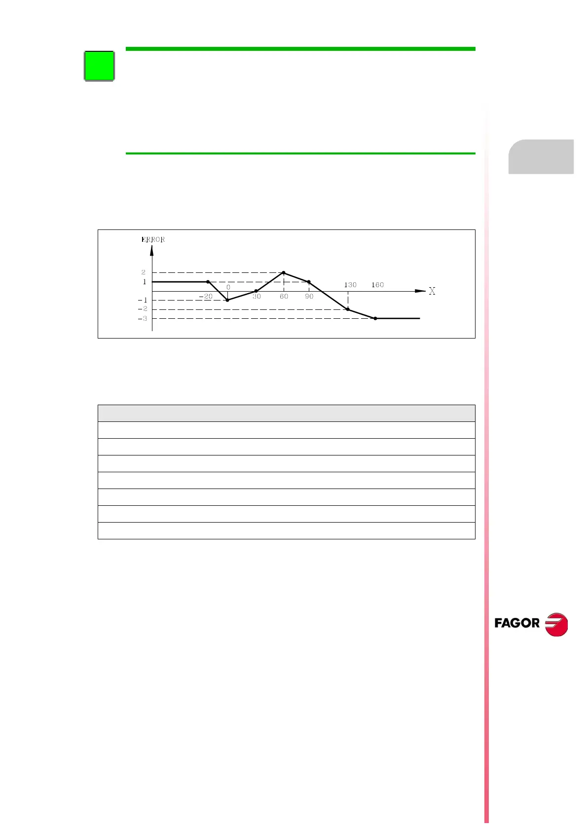
Setting example:
The X axis ballscrew must be compensated in the positive direction for between X-20 and X160
according to the leadscrew error graph below:
Set a.m.p. LSCRWCOM (P15) = ON and NPOINTS (P16) = 7
Considering that the Machine Reference Point (physical location of the marker pulse) is located 30
mm from HOME (machine reference zero), at X30. The leadscrew error compensation parameters
must be set as follows:
Bidirectional compensation of the leadscrew error is available from versions V7.11
(mill) and V8.11 (lathe) on.
When updated from a version that does not have bidirectional compensation, it keeps
the error values in the positive direction and it sets a zero error in the negative direction
for all the points.
When changing to a version that does not have bidirectional compensation, it keeps
the error values in the positive direction, but it loses the error values in the negative
direction. Also, the amount of error for the machine reference point must be zero.
Point Position Positive error Negative error
P001 X -20,000 EX 0,001 EX 0
P002 X 0,000 EX -0,001 EX 0
P003 X 30,000 EX 0,000 EX 0
P004 X 60,000 EX 0,002 EX 0
P005 X 90,000 EX 0,001 EX 0
P006 X 130,000 EX -0,002 EX 0
P007 X 160,000 EX -0,003 EX 0
 Loading...


