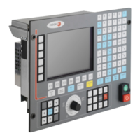
Installation manual
CNC 8035
CONCEPTS
Digital CAN servo
5.
(SOFT M: V15.3X)
(S
OFT T: V16.3X)
·241·
Cyclic channel. Write variables for the CNC-PLC
plc.m.p. SWR800 (P68) through SWR819 (P87) indicate which type of information has been put
in registers R800 through R819 and which drive will be assigned that value.
These parameters are set in 1.5 format. The units digit identifies the drive (node) supplying the data
and the decimals indicate the identifier number (see table below).
For example, "P70=2.34178" indicates that the value of PLC register R802 will be assigned to the
"DigitalOutputsValues" of the drive located in bus node 2.
The type of information available and its associated identifiers are:
The "VelocityCommand" variable can be modified for the axes that have been selected as DRO axes,
by a.m.p. DROAXIS (P4) or via PLC by activating the logic CNC axis input "DRO1,2,3,...".
Service channel
The service channel can only be accessed through a high-level block of a part-program, a PLC
channel or a user channel. All variables can be accessed except the string type appearing in the
drive manual.
• Reading and writing from a part-program or from a user channel.
• Reading and writing from the PLC channel.
P68=>R800 P69=>R801 P70=>R802 P71=>R803 etc.
To identify the units of the variables, see the drive manual.
Type of information Identifier
DA1Value 34176
DA2Value 34177
DigitalOutputsValues 34178
VelocityCommand 00036
Read: (P*** = SVARaxis **)
Write: (SVARaxis** = P**)
Example: (P110 = SVARX 40)
It assigns to parameter P110 the value of the X axis variable with the identifier
40 which corresponds to "VelocityFeedback"
Read: ... = CNCEX ((P*** = SVARaxis***), M1)
Write: ... = CNCEX ((SVARaxis** = P***), M1)
Example: ... = CNCEX (( SVARX 100= P120 ),M1
It assigns the value of parameter P120 to the X axis variable with identifier 100
(VelocityProportionalGain).

 Loading...