Installation manual
CNC 8035
CNC CONFIGURATION
CNC structure
1.
(SOFT M: V15.3X)
(S
OFT T: V16.3X)
·55·
DIGITAL DRIVES
Digital CAN servo system
Digital servo is being used to communicate with Fagor drives.
• CAN field bus and standard CanOpen communication protocol.
Module identification at the bus
Each one of the elements integrated into the CAN bus is identified by the 16-position rotary switch
(0-15) "Address" (also referred to as "Node_Select"). This rotary switch selects the address (node)
occupied by each element integrated in the bus.
Although the switch has 16 positions, only positions 1 through 8 are valid. The CNC does not have
a switch, The drives occupy consecutive positions (recommended) starting from ·1·.
The corresponding drive must be turned off and back on (or press the Reset button) for the address
change to be assumed.
The "Line_Term" switch
The "Line_Term" switch identifies which are the elements that occupy the ends of the CAN bus; i.e.
the first and last physical element in the connection.
The central unit must always be at one end of the line. The other end will be the last one of the remote
module groups.
The switch position of the terminating elements must be "1" and that of the rest of the elements "0".
The CNC does not have a switch and always has the terminating resistor activated.
Characteristics of the CAN cable
Use a specific CAN cable. The ends of all the wires and the shield must be protected by the
corresponding pin. Also use the pins to secure the cable to the connector.
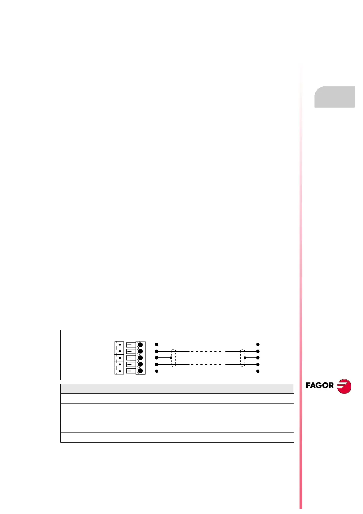
CAN connector pinout
5-pin male Phoenix minicombicon connector (3.5 mm pitch).
The connector has two shield pins. Both pins are equivalent; the CAN shield may be connected to
either one.
Interconnection of modules
It is connected in series. The figure shows the CAN connection between the central unit and 2 drives.
Type: Shield. Twisted pairs (1 x 2 x 0,22 mm
2
).
Flexibility: Superflexible. Minimum static bending radius of 50 mm and
a dynamic radius of 95 mm.
Cover: PUR
Impedance: Cat.5 (100 - 120 )
Signal Description
ISO GND Ground / 0 V.
CAN L Bus signal (LOW).
SHIELD CAN shield.
CAN H Bus signal (HIGH).
SHIELD CAN shield.
CAN L
SHIELD
CAN H
SHIELD
ISO GND
1
2
3
4
5
1
2
3
4
5
Pin Pin