Installation manual
CNC 8035
MACHINE AND POWER CONNECTION
Connection of the emergency input and output
3.
(SOFT M: V15.3X)
(S
OFT T: V16.3X)
·71·
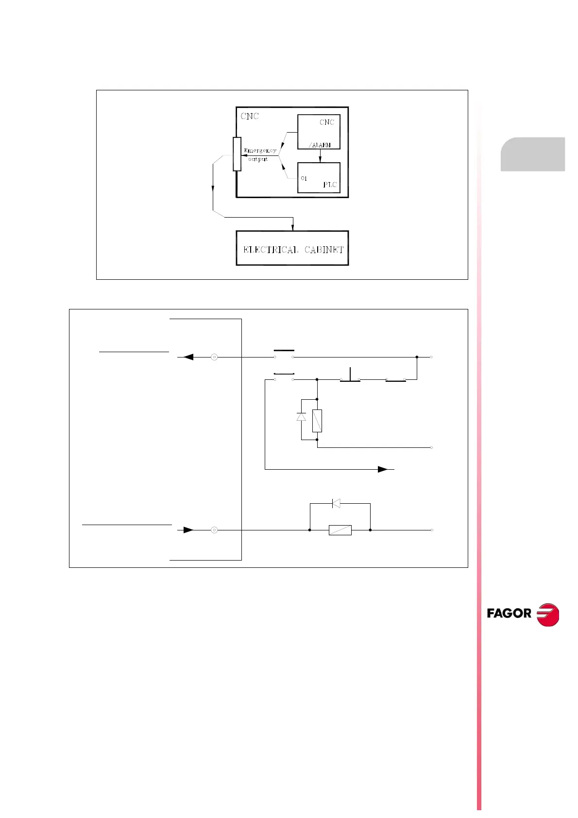
When the CNC detects an error, it will indicate it to the PLC with the general logic output “/ALARM"
and it will set the emergency output low (pin 2 of connector X2).
Since this signal corresponds to the PLC output O1, it can also be activated by the PLC program.
The recommended connection diagram is the following:
Emergency STOP
Emergency output
Emergency STOP relay
Emergency from
electrical cabinet
Other emergency
buttons
O1
I1
RE
RSE
RSE
0 V
24 V
0 V
RE
Emergency
STOP button