12530/12540 OWNER'S MANUAL
P/N 447203 Issue I IV-7
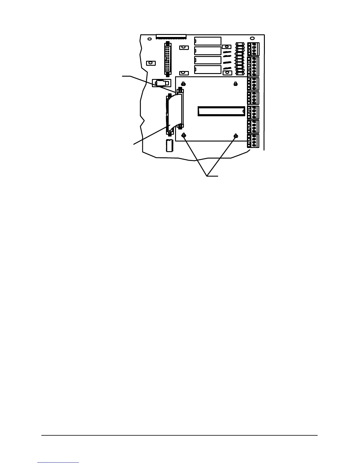
G. Loop Driver Board Installation
1. Set jumpers J1-J5 to the “F” position for Faraday or to “S” for System Sensor addressable devices.
2. Using four Plastic Spacers (P/N 943165), attach the Loop Driver Board (P/N 413765) to the Main
Termination Board.
3. Plug the Cable Assembly (P/N 446653) into connector P1 of the Loop Driver Board and to connector
P7 of the Main Termination Board.
Loop Board
Spacers (4)
TB1
P1
TB3
TB9
TB7
OUT
2
1
OUT
IN
2
2-
2
2-
OUT
IN
A
A
B-
B
NAC
NAC
D-
D
+
-
P2
P3
P4
X
X-
-
OUT
1
X
-
Cable Assembly