12530/12540 OWNER'S MANUAL
P/N 447203 Issue I IV-9
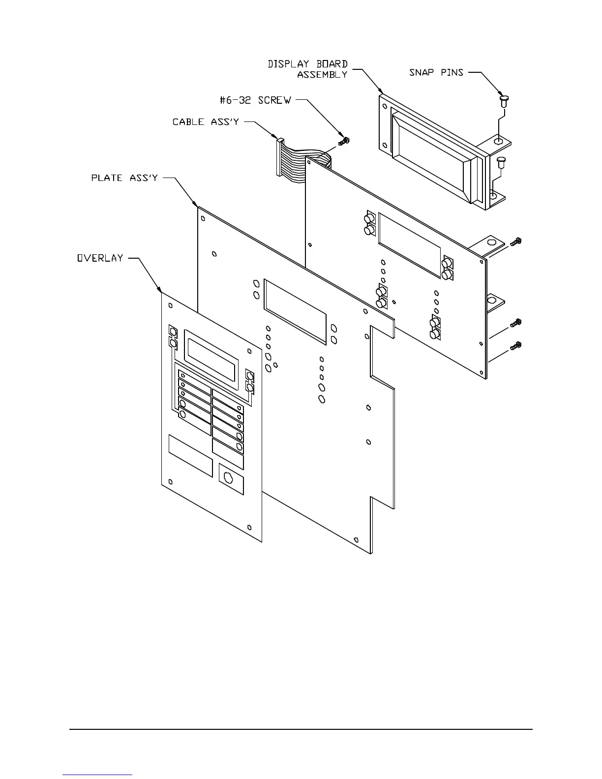
I. Front Plate Assembly
1. Secure Main Logic Board (P/N 413764) to Plate Assembly using six #6-32x1/4” screws (P/N29529-
11).
2. Apply Overlay (P/N 447206) to Plate Assembly (P/N 446668).
3. Using two snap pins (P/N 944043), attach the Display Board (P/N 413526) to the mounting brackets
on the Main Logic Board.
4. Plug the Cable Assembly (P/N 446649) into connector P2 of the Display Board and to connector P2
of the Main Logic Board.