12530/12540 OWNER'S MANUAL
P/N 447203 Issue I V-3
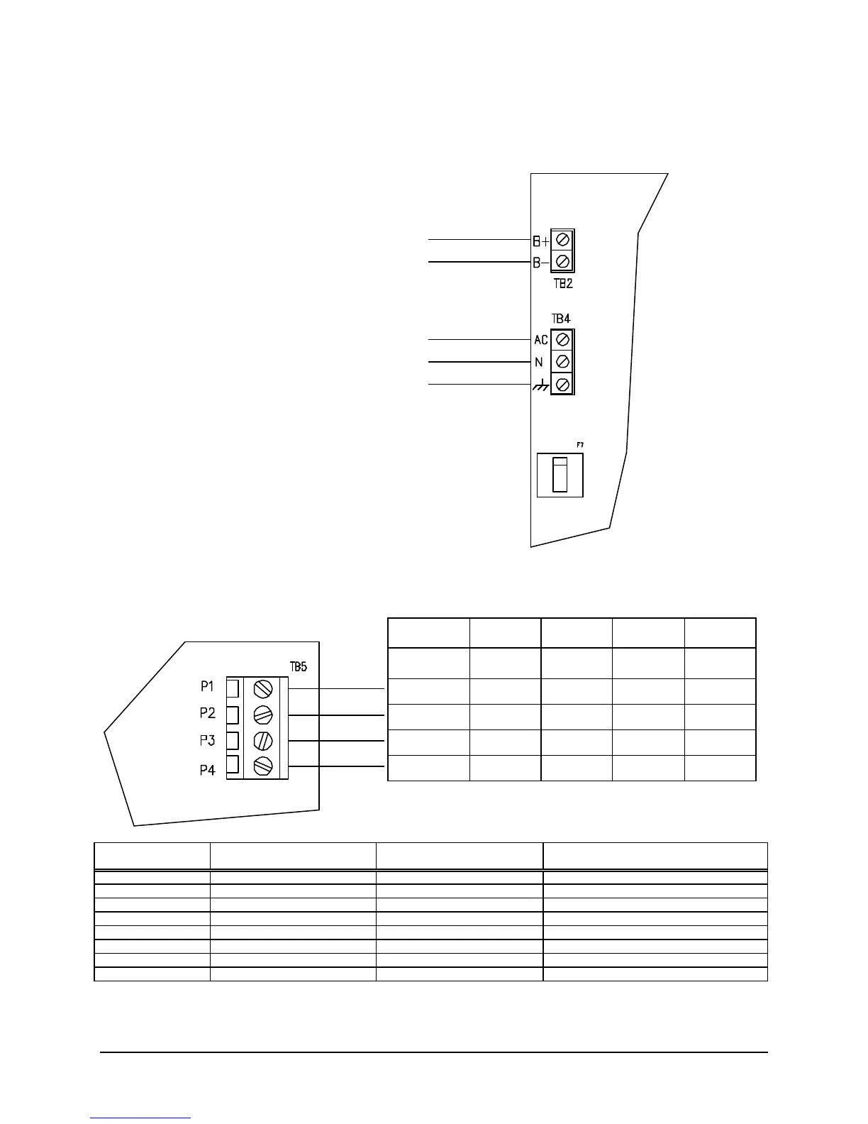
PRIMARY AND SECONDARY POWER WIRING
The AC main connections and the battery connections must be made along the left-hand side of the
board. Route all high voltage and non-power limited wiring together and away from power limited wiring.
PRINTER WIRING
The printer connections must be made along the right-hand side of the board. The RS232 output
provides event data for connection to a printer, terminal or computer.
Faraday RPR-100
DIP Switch Settings
Control Board Serial Board
Switch Bank 1
Serial Board
Switch Bank 2
SW-1 ON-Language (Unlashed 0) ON-Odd Parity ON-4800 bps
SW-2 OFF-Language (Unlashed 0) ON-No Parity OFF-4800 bps
SW-3 OFF-Language (Unlashed 0) ON-8 Bit Data ON-4800 bps
SW-4 OFF-Form Length (11”) ON-Ready/Busy OFF-DSR Inactive
SW-5 ON-Form Length (11”) ON-Diagnostic-Circuit Test ON-Buffer Threshold (32 bytes)
SW-6 ON-Auto Line Feed (ON) ON-Normal Print Mode OFF-Busy Signal Timing (1S)
SW-7 ON-Data Bits (8) ON-DTR ON-DTR Signal (space after power on)
SW-8 ON-Front Panel (Disable) ON-DTR OFF-Not Used
(7 to 38AH)
Supervised
Non-Power Limited
3A/1.5A max., Supervised
Non-Power Limited
N
GND
Keep All Non-Power Limited Wiring
Separate from Power Limited Wiring
B-
Function
Function
Terminal
Terminal
Male
9-Pin
Male
25-Pin
Female
9-Pin
CTS DTR 8 20 4
TXD RXD 2 3 2
RXD TXD 3 2 3
GND GND 5 7 5
Settings: 4800 bps, 8 data bits, 1 stop bit, no parity