12530/12540 OWNER'S MANUAL
P/N 447203 Issue I V-5
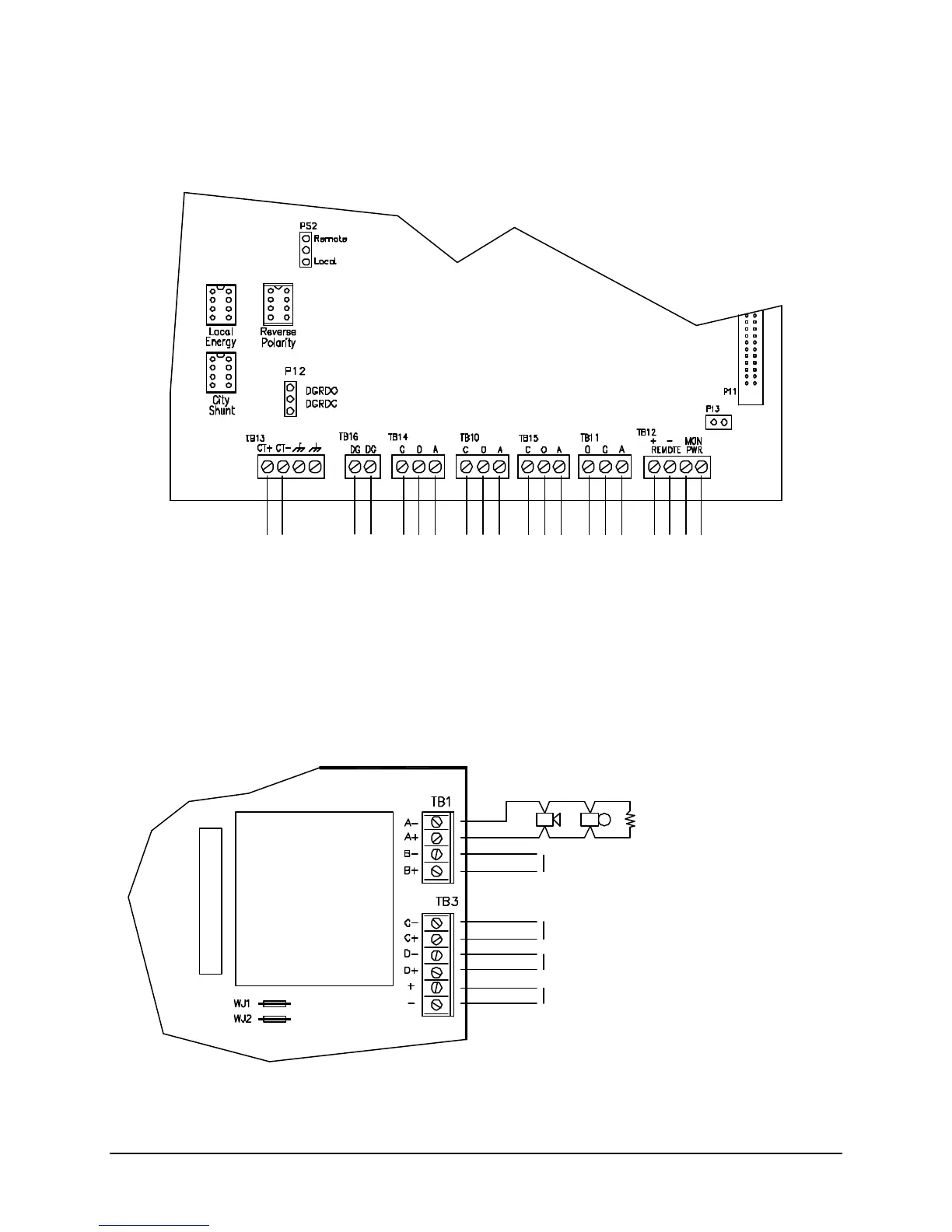
CITY TIE AND STATUS RELAYS WIRING
The lower edge of the main termination board provides for connection of city tie, status relay contacts,
auxiliary power connections and external trouble monitor.
NAC WIRING
At the right hand side of the main board the terminal blocks are used for the connection of notification
appliances. Four individual NACs marked A through D are provided and the polarity shown is when the
NAC is activated.
Notification Appliance Circuit
Style Y, Class B
Supervised, Power Limited
See Owner’s Manual for
Compatible Devices
Faraday P/N 10812
Polarity shown in activated condition
Wiring above
Wiring above
Alarm Voltage: 24VDC nominal
Max. Alarm Current: 1.5A
Max. Ripple: 1.5VAC
Max. Wire Voltage Drop: 1.0VDC
Max. Standby Current: 3.4mA
NOTE:
The maximum current for control
unit and appliances is 4.4A
Wiring above
nominal input for NACs 3 & 4,
3 Amp. max.
Use 12408 Auxiliary Power Supply.
Cut jumper WJ1 & 2 to enable
Class A Adapter
Alarm
Trouble Supervisory
Supervised, Power Limited
If P13 removed, monitors
normally closed contact
(Shown in normal standby condition)
2A@30VDC, 0.5A@30VAC max, Resistive
For Power Limited Source, Unsupervised
Auxiliary Power Output 0.9A max.@24VDC
nominal, Unsupervised, Power Limited
(Maximum current of all auxiliary power
outputs, DACT and relay board is 0.9A.)
Failure
Connections
Failure
+ -