12530/12540 OWNER'S MANUAL
P/N 447203 Issue I VIII-2
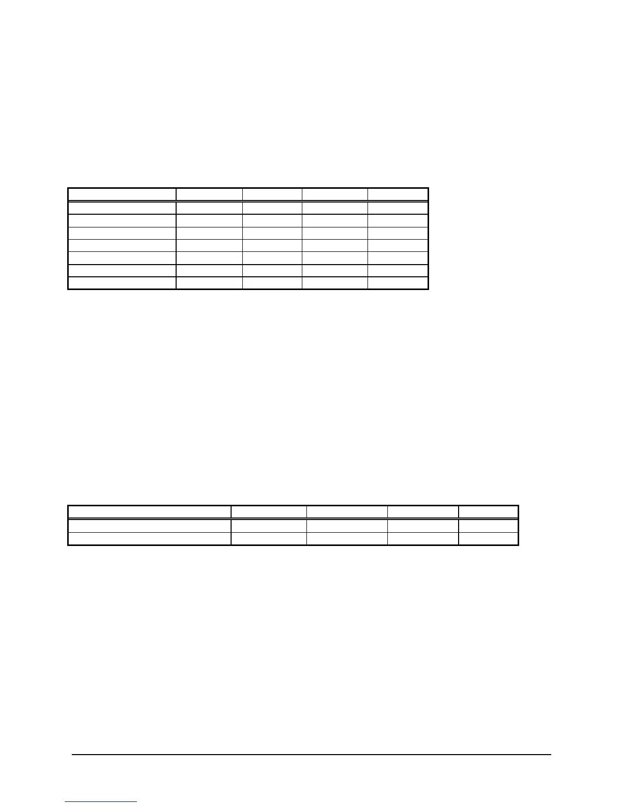
Notification Appliance Circuit Wire Selection Guide
Each Notification Appliance Circuit must not have a voltage drop greater than 1 volt. The following chart
is based on the following premises:
• The entire load is at the end of the wire run (worst case).
• Resistance is of solid copper wire
Contact your local distributor or the factory if further information is needed in your circumstances.
Maximum Wire Loop Distance (Feet)
Signal Load (A) 18 AWG 16 AWG 14 AWG 12 AWG
0.1 1,237 1968 3134 4975
0.25 495 787 1253 1990
0.5 247 393 626 995
0.75 165 262 417 663
1.0 123 196 313 497
1.25 99 157 250 398
1.5 82 131 208 331
Addressable Device Circuit Wire Selection Guide
Each addressable device circuit must meet the following requirements:
• Total loop resistance - 40 ohm maximum.
• Total loop capacitance - 0.28uF maximum (56pF/ft. max.)
• Twisted pair wire.
• Unshielded cable.
• Low capacitance cable.
• High velocity of propagation cable - 60% minimum.
• Each loop runs separate from all other circuits.
• Run + out and - out separately from + in and - in.
• Different models or types of cable should not be in the same loop.
Maximum Wire Loop Distance (Feet)
(Includes all branches of a Style 4 loop)
Wire size: 18AWG 16AWG 14AWG * 12AWG
Wire length: 6150 9750 10,000 10,000
Cable length: 3075 4875 5,000 5,000
* The terminal blocks of Faraday addressable devices are rated for a maximum of 14AWG wire.