12530/12540 OWNER'S MANUAL
P/N 447203 Issue I VI-5
SERIAL RELAY UNIT SWITCHES
Switches are standard 4-position DIP switches. Slide the switches to the left for Off and to the right for
On. All DIP switches are factory set for off, verify proper settings for proper system operation.
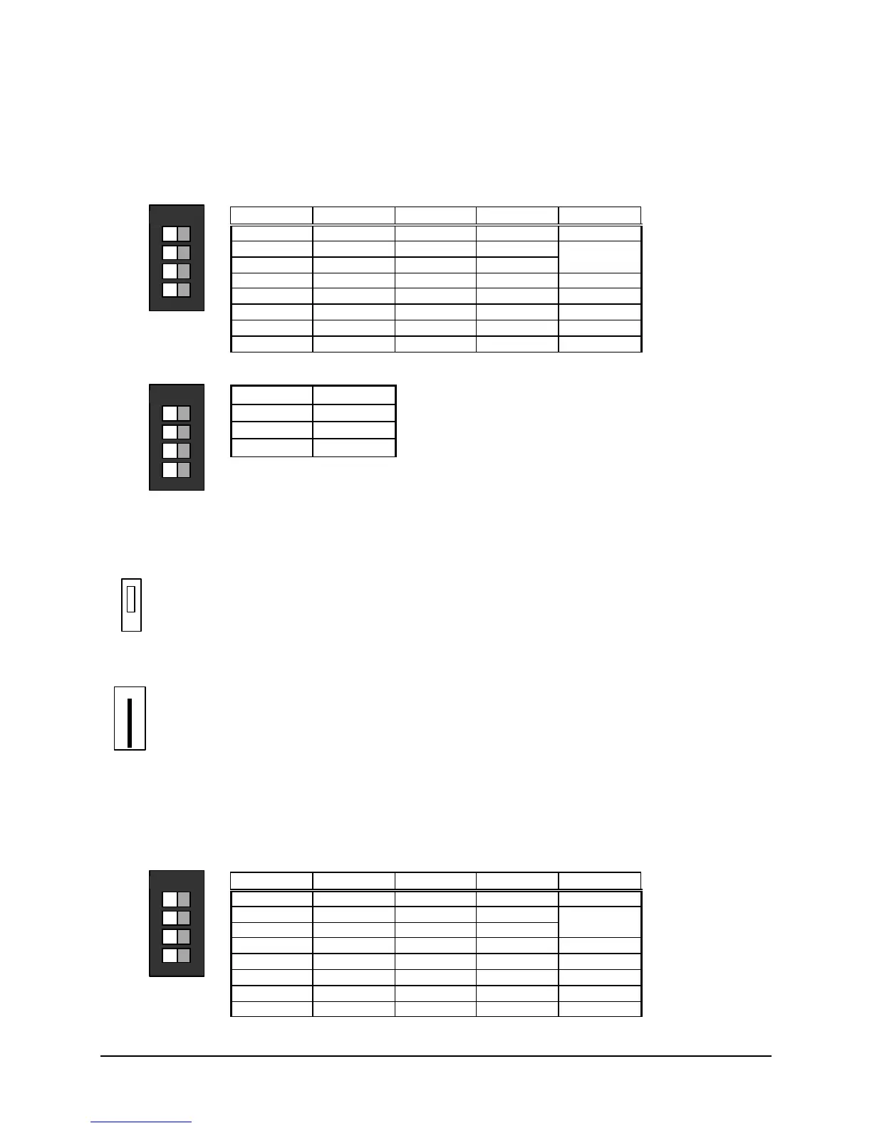
SW1 – Address Selection (Remote Processor Board)
Address SW1-1 SW1-2 SW1-3 SW1-4
1 ON ON ON Not used
2 OFF ON ON Not used
3 ON OFF ON Not used
4 OFF OFF ON Not used
5 ON ON OFF Not used
6 OFF ON OFF Not used
7 ON OFF OFF Not used
8 OFF OFF OFF Not used
SW1 – Relay Group Selection (Serial Relay Board)
Note: Only one switch should be activated on each serial relay board.
SW1-1
1-8
SW1-2
9-16
SW1-3
17-24
SW1-4
Not used
SERIAL ANNUNCIATOR UNIT JUMPERS
Factory setting is shown.
P6 – Buzzer Selection (Remote Processor Board)
• Local
•
• Remote
WJ1 – External Power Input (cut jumper if auxiliary power supply is used) (Remote Processor Board)
WJ1
SERIAL ANNUNCIATOR UNIT SWITCHES
Switches are standard 4-position DIP switches. Slide the switches to the left for Off and to the right for
On. All DIP switches are factory set for off, verify proper settings for proper system operation.
SW1 – Address Selection (Remote Processor Board)
Address SW1-1 SW1-2 SW1-3 SW1-4
1 ON ON ON Not used
2 OFF ON ON Not used
3 ON OFF ON Not used
4 OFF OFF ON Not used
5 ON ON OFF Not used
6 OFF ON OFF Not used
7 ON OFF OFF Not used
8 OFF OFF OFF Not used